3 digital input circuits – Yaskawa MP2000 Series I/O Module User Manual User Manual
Page 93
4.2 Specifications of LIO-06 Module Connections
4.2.3 Digital Input Circuits
93
4
LIO-06 Module
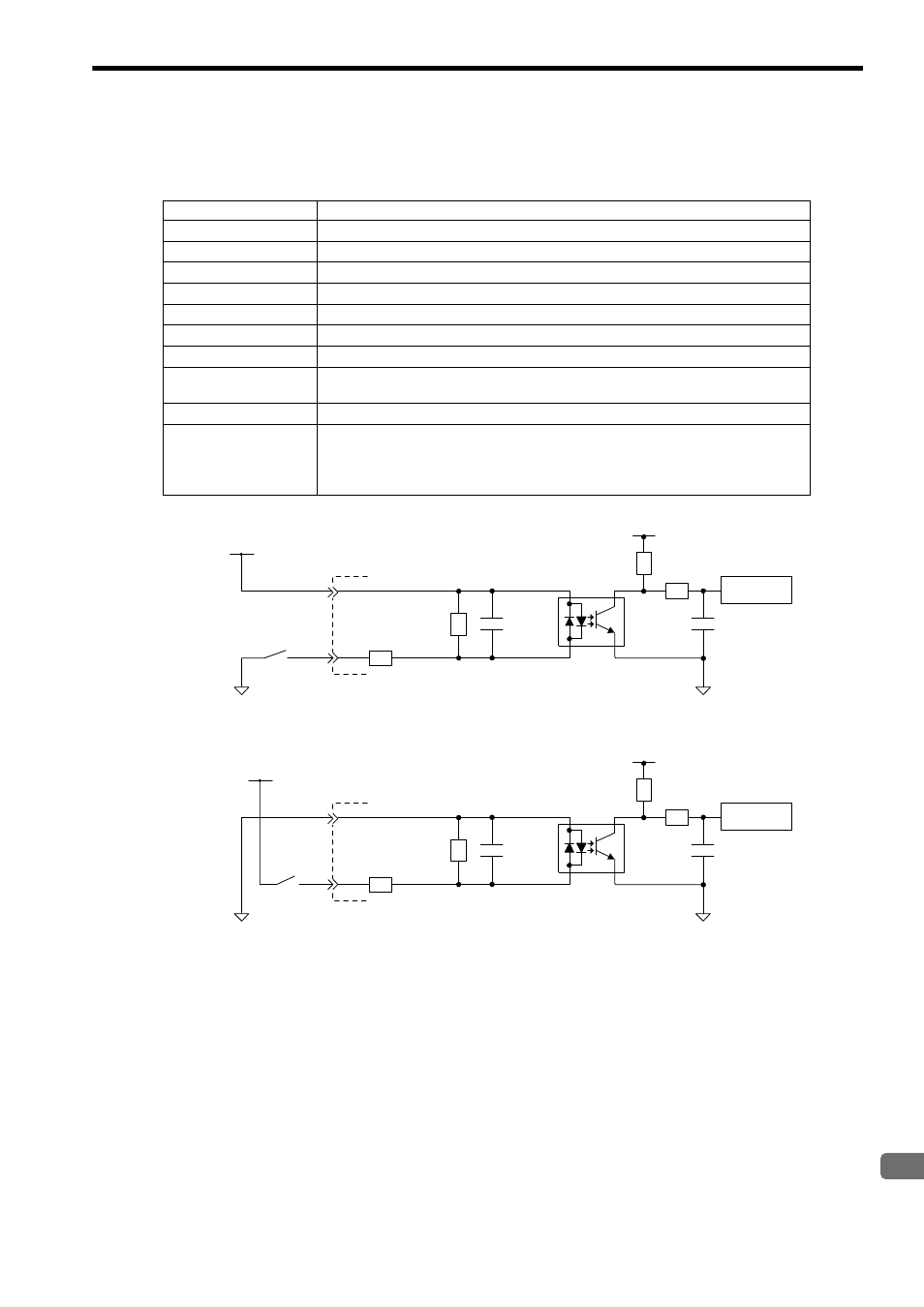
4.2.3 Digital Input Circuits
The following table shows the LIO-06 Module digital input circuit specifications.
Fig. 4.2 Digital Input Circuit (Sink Mode Input)
Åj
Fig. 4.3 Digital Input Circuit (Source Mode Input)
Item
Specifications
Inputs
8 points
Input Format
Sink mode/source mode input
Isolation Method
Photocoupler
Input Voltage
24 VDC, +10/–20% (+19.2 to +26.4 V)
Input Current
4.1 mA (typ.)
ON Voltage/Current
15 V min./2.0 mA min.
OFF Voltage/Current
5 V max./1.0 mA max.
ON Time/OFF Time
ON: 0.5 ms max.
OFF: 0.5 ms max.
Number of Commons
1 (8 points/common)
Other Functions
• DI_00 is shared with an interrupt input. If DI_00 is turned ON while interrupts are
enabled, the interrupt processing drawing (program) is executed.
• DI_01 is shared with pulse latch inputs. If DI-01 is turned ON while pulse latch inputs are
enabled, the pulse counter will be latched.
5.6k
Ω
Vcc
DI_COM
+24V
DI_IN
Internal
circuit
0
24
R
R
R
R
5.6k
Ω
Vcc
DI_COM
+24V
DI_IN
Internal
circuit
0
24
R
R
R
R