Main logic loop, Backplane data transfer, 2 backplane data transfer – ProSoft Technology PTQ-101M User Manual
Page 114
PTQ-101M ♦ Quantum Platform
Reference
IEC 60870-5-101 Master Communication Module
Page 114 of 181
ProSoft Technology, Inc.
May 14, 2008
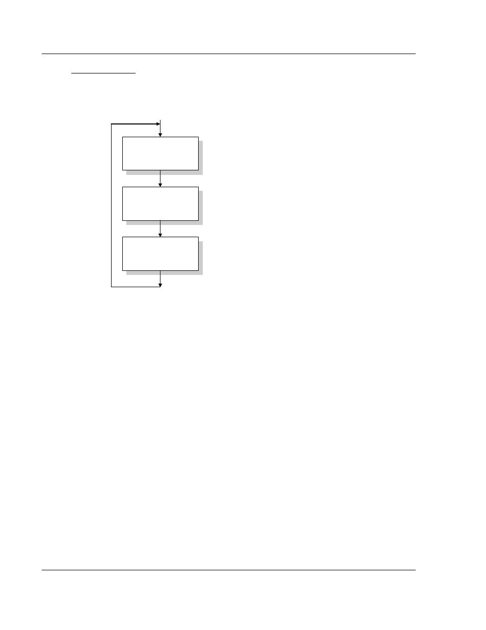
Main Logic Loop
Upon completing the power up configuration process, the module enters an
infinite loop that performs the following functions:
Call I/O Handler
Call CFG/DEBUG Port
Driver
Call Network Master
Drivers
Call I/O Handler
Transfers data between the module and processor
(user, status, etc.)
Call Serial Port Driver
Rx and Tx buffer routines are interrupt driven. Call to
serial port routines check to see if there is any data
in the buffer, and depending on the value, will either
service the buffer or wait for more characters.
Call Network Master Drivers
Generate Messages.
From Power Up Logic
7.2.2 Backplane Data Transfer
The current version of the PTQ-101M backplane driver (version 2.10 or newer),
uses a Large I/O model, which differs from previous versions of the backplane
driver in that it transfers all of the data in the Read and Write databases between
the module and the processor on every scan.
The [Backplane Configuration] section of the configuration file defines the starting
registers for read and write operations, as well as the number of registers to use
for each data area.
#These values are required to define the data area to transfer between the
#module and the processor.
Read Register Start : 0 #Database start register to move to processor
Read Register Count : 50 #Number of words moved from module to
#processor
Write Register Start: 1000 #Database start register where data placed
#from processor
Write Register Count: 50 #Number of words moved from processor to
#module
Pass-Through Events : N #Pass event messages to processor (N =No events
#will be passed to the processor, Y=Yes will be
#passed to the processor consuming block 9903
#Used to define the area in the Processor for the module to interface with
3x Register Start: 1 #3x start register where data moved from
#module to processor (1 to n)
4x Register Start: 1 #4x start register where data moved from
#processor to module (1 to n)