Processor module – ProSoft Technology PTQ-101M User Manual
Page 117
Reference PTQ-101M
♦ Quantum Platform
IEC 60870-5-101 Master Communication Module
ProSoft Technology, Inc.
Page 117 of 181
May 14, 2008
3
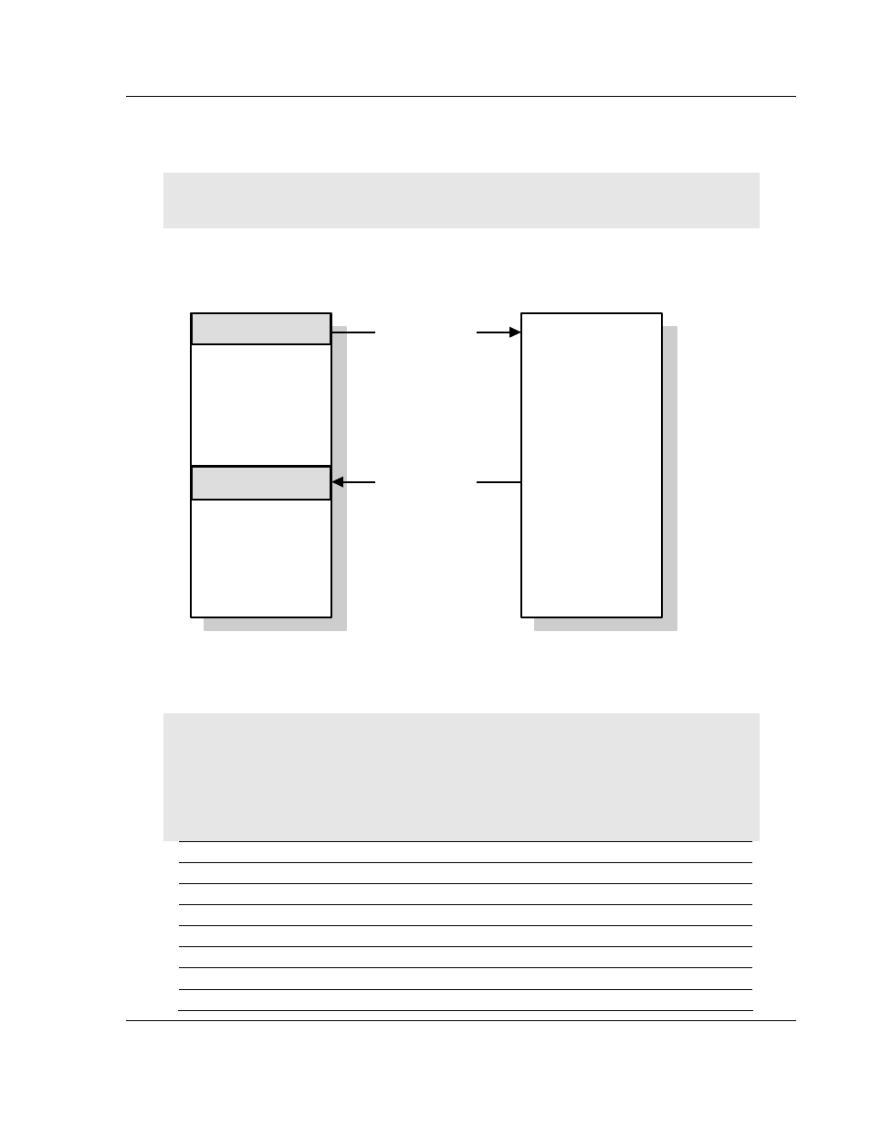
If the input block sequence number equals the output block sequence
number + 1, copy the block response to appropriate variables in the module's
memory.
Note: Command Control blocks are not copied to the module database. You must define variables
in the module's main memory, and use processor logic to process the command control request.
Step 2
Process Command
Control Request
Processor
Module
Step 1
Command Control
Request
Step 3
Command Control
Response
Words 1 to 64
Command Control
Words 1 to 64
Command Control
Words 65 to 164
Holding Register
(Write area)
Words 65 to 164
Input Register
(Read area)
The following table shows the contents of the command control area when a
command control block such as 9970 (Read Module's Time to Processor) is
issued.
Note: The diagram above shows the memory addresses for a Quantum processor. If you are
deploying the PTQ-101M with a Unity processor, substitute %MW for read only data, and %IW for
read/write data.
Note: The processor memory locations in the example tables below use the 3x register start and
4x register start values defined in Backplane Data Transfer. You can configure any valid 3x and
4x start address that is not used by other processes.
Command Control Word
Description
40001
Output sequence number
40002 Block
ID
40003
Block request word 1
40004
Block request word 2
40005
Block request word 3
… …
40064
Block request word 62