Command control block – ProSoft Technology PTQ-101M User Manual
Page 116
PTQ-101M ♦ Quantum Platform
Reference
IEC 60870-5-101 Master Communication Module
Page 116 of 181
ProSoft Technology, Inc.
May 14, 2008
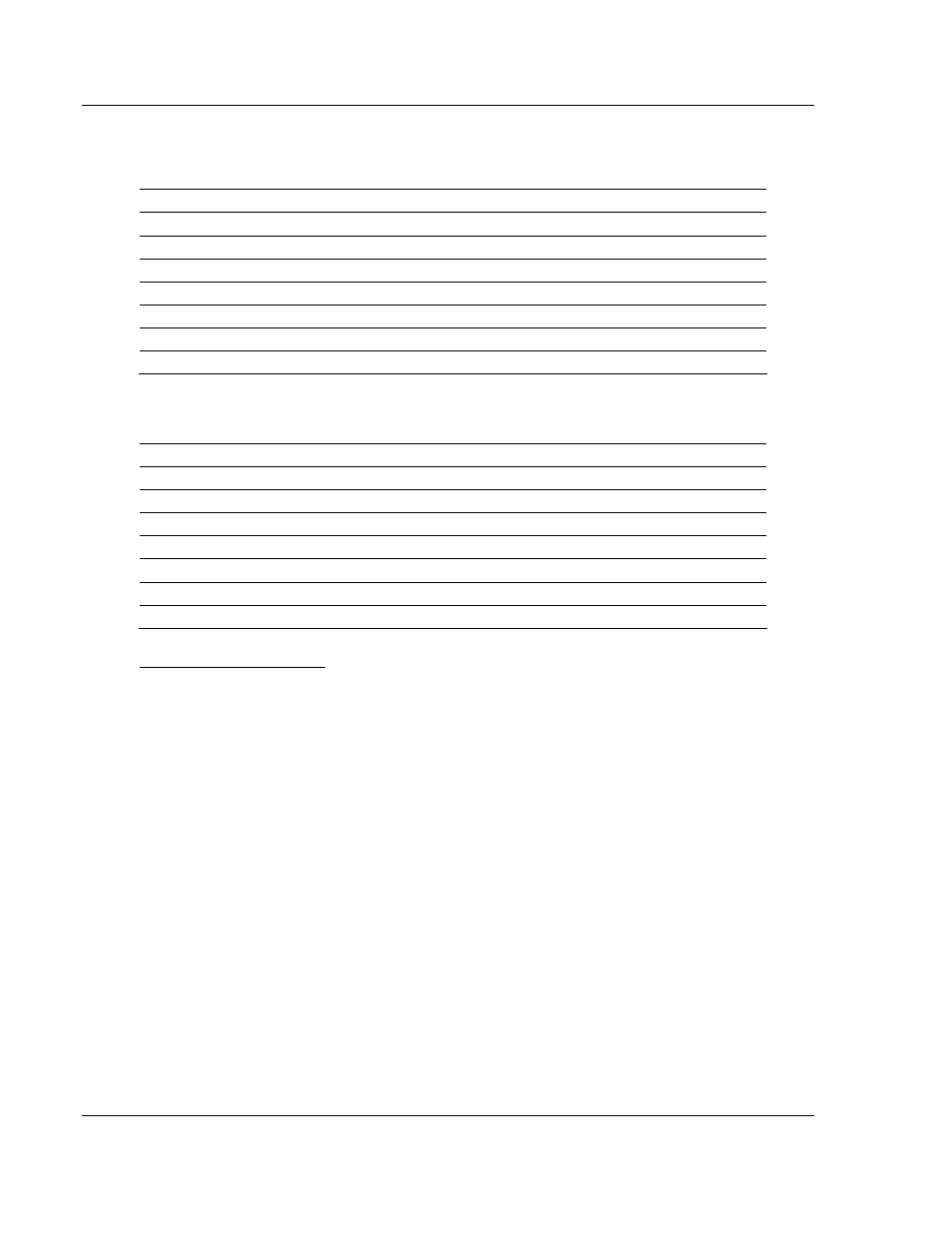
The data mapping in the following example shows the relationship between
processor and PTQ-101M memory addresses, assuming a 4x register start value
of 40001 and a PTQ-101M database start value of 0.
Processor Memory Address
Module Database Address
40065
0
40066
1
40067
2
40068
3
40069
4
… …
40164
99
The data mapping in the following example shows the relationship between
processor and PTQ-101M memory addresses, assuming a 3x register start value
of 30001 and a PTQ-101M database start value of 2000.
Processor Memory Address
Module Database Address
30065
2000
30066
2001
30067
2002
30068
2003
30069
2004
… …
30164
2099
Command Control Block
The first 64 words of each block are reserved for command control. Each
command control block has a Block ID number (shown in parentheses below)
that identifies the command control instruction. The PTQ-101M module supports
the following command control blocks:
Status Block (9250)
User Constructed Command block (9901)
Command Control Block (9902)
Events messages from Master port (9903)\
Command List Error data (9950)
Read Module's Time to Processor (9970)
Set Module's Time Using Processor Time (9971)
Warm Boot (9998) or Cold Boot (9999)
The value in word 0 of this 64 word block is the block sequence number. This
number identifies whether the contents of the block have changed. This is the
actual trigger to send the control request to the module.
Processor logic must be built to handle the command control functionality. The
logic would typically follow these steps:
1
Move the block request to output command control area.
2
Move a new value to the output block sequence number.