Data exchange – ProSoft Technology PTQ-101M User Manual
Page 115
Reference PTQ-101M
♦ Quantum Platform
IEC 60870-5-101 Master Communication Module
ProSoft Technology, Inc.
Page 115 of 181
May 14, 2008
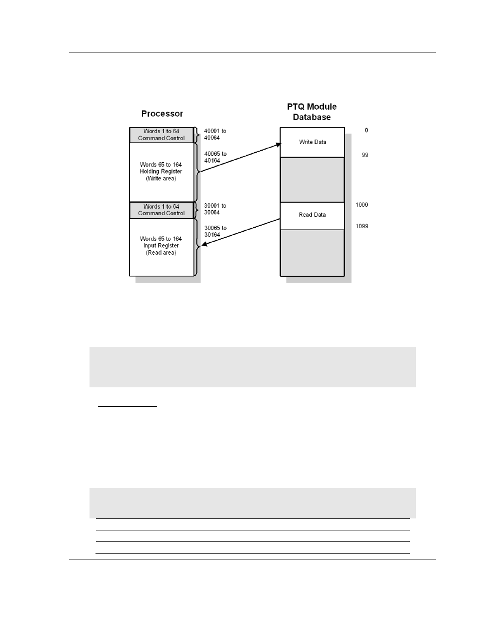
The values in the example configuration file section above are illustrated in the
following diagram.
The module transfers the entire read and write areas at the end of every
processor scan. The module will hold the processor scan for a certain period of
time, which allows the module to transfer the entire read and write areas. This
means that the larger the read and write areas, the longer the processor scan
time will be.
Note: The diagram above shows the memory addresses for a Quantum processor. If you are
deploying the PTQ-101M with a Unity processor, substitute %MW for read only data, and %IW for
read/write data.
Data Exchange
The module transfers all the configured read or write data at the end of each
processor scan. You can configure up to 4000 words in each direction. The more
data you configure, the longer the processor scan will be.
Words 0 through 63 in each read/write block are reserved for command control.
Refer to Command Control (page 131) for more information on command control
blocks. The following table shows the relationship between the processor
memory and the module database areas.
Note: Refer to Backplane Data Transfer (page 114) for the example configuration values that are
used in the following tables.
Module Database
Register
Unity Register
Description
Read Data
3x
%IW
Input Register
Write Data
4x
%MW
Holding Register