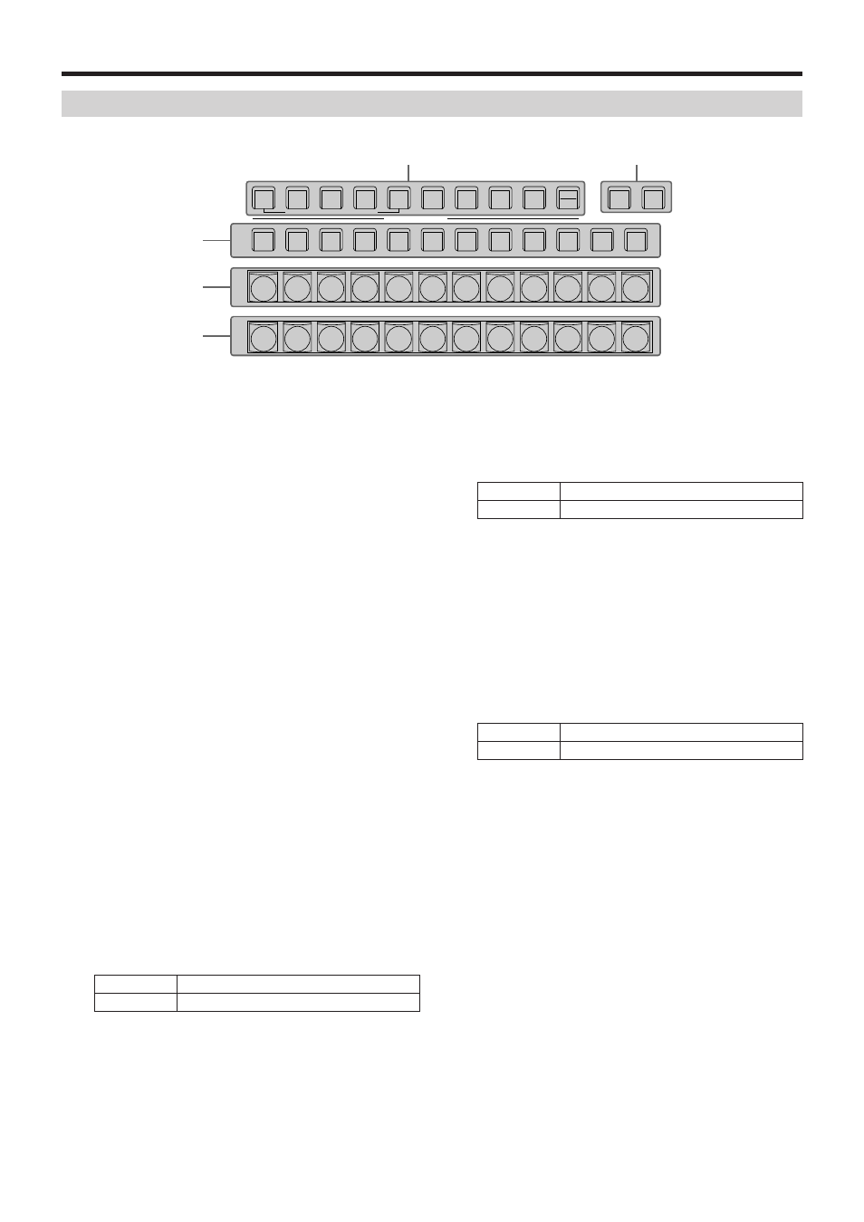
Crosspoint area, Parts and their functions, 4 pgm/a bus crosspoint buttons [pgm/a 1 to 12 – Panasonic AV-UHS500 12G-SDI/HDMI UHD 4K Compact Live Switcher User Manual
Page 18: 5pst/b bus crosspoint buttons [pst/b 1 to 12, 6aux bus selector buttons (aux bus delegation), 7aux bus crosspoint buttons
18
Parts and their functions
Crosspoint area
KEY1
F/S
PGM
A
PST
B
KEY2
F/S
KEY3
F/S
DSK1
F/S
DSK2
F/S
DISP
CAM
AUX BUS DELEGATION
1/13
2/14
3/15
4/16
5/17
6/18
7/19
8/20
9/21
10/22
11/23
12/24
AMBER : FILL / GREEN : SOURCE
AUX1
AUX
AUX2
AUX3
AUX4
SHIFT
SHIFT
SHIFT
MV1
MV2
PGM
PVW
AUX /DISP SOURCE
4
PGM/A bus crosspoint buttons
[PGM/A 1 to 12]
These are used to select the PGM/A bus video signals.
Buttons 1 to 24 can be selected using the [SHIFT] button.
Refer to “Selecting the bus using the SHIFT function”.
“A/B”, “PGM-A/PST-B” or “PGM-B/PST-A” can be selected
as the Bus Mode item by selecting the Config menu
following by the Operate sub menu.
Refer to “Selecting the bus mode”.
When one of the crosspoint buttons (
4
,
5
,
7
) is held
down, the name of the input material and the number of
the crosspoint button are displayed.
5
PST/B bus crosspoint buttons
[PST/B 1 to 12]
These are used to select the PST/B bus video signals.
Buttons 1 to 24 can be selected using the [SHIFT] button.
Refer to “Selecting the bus using the SHIFT function”.
“A/B”, “PGM-A/PST-B” or “PGM-B/PST-A” can be selected
as the Bus Mode item by selecting the Config menu
following by the Operate sub menu.
Refer to “Selecting the bus mode”.
6
AUX bus selector buttons
(AUX BUS DELEGATION)
Select the bus to be operated using the AUX bus
crosspoint buttons (
7
).
The selected button lights.
[KEY1 F/S], [KEY2 F/S], [KEY3 F/S]:
This button is used to change the AUX bus crosspoint
buttons (
7
) into the source selector buttons for the key
fill buses or key source buses.
Each time it is pressed, the selector button function
is switched between the key fill buses and key source
buses.
Amber
Key fill buses
Green
Key source buses
[DSK1 F/S], [DSK2 F/S]:
This button is used to change the AUX bus crosspoint
buttons (
7
) into the source selector buttons for the DSK
fill buses or DSK source buses.
Each time it is pressed, the selector button function is
switched between the DSK fill buses and DSK source buses.
Amber
DSK fill buses
Green
DSK source buses
[AUX1] to [AUX4]:
These buttons are used to change the AUX bus
crosspoint buttons (
7
) into the selector buttons for the
sources of the AUX buses.
[DISP/CAM] (built-in display/CAM):
When the built-in display is selected, this switches the
AUX crosspoint buttons (
7
) to DISP bus (the images
displayed on the built-in display) source selector buttons.
When CAM is selected this switches the AUX crosspoint
buttons (
7
) to CAM source selector buttons.
The selection switches between built-in display and
CAM each time you press the button.
Amber
Built-in display selected
Green
CAM selected
7
AUX bus crosspoint buttons
These buttons are used to select the source of the bus
which was selected by the AUX bus selector button (
6
).
Buttons 1 to 24 can be selected using the [SHIFT] button.
Refer to “Selecting the bus using the SHIFT function”.
8
Dedicated crosspoint buttons for the AUX/DISP
bus (AUX/DISP SOURCE)
While the [AUX1] to [AUX4] AUX bus selector buttons (
6
)
are illuminated, these select AUX bus sources.
While the [DISP/CAM] AUX bus selector button (
6
) is
illuminated, it selects DISP bus sources.
The buttons that are pressed turn amber.
[MV1/MV2]:
Selects either multi view display signal 1 or signal 2 for
the AUX bus or the DISP bus.
Switching between multi view display signal 1 and 2 is
done with the [SHIFT] button (
7
).
[PGM/PVW]:
Selects either the PGM signal or the PVW signal for the
AUX bus or the DISP bus.
Switching between the PGM signal and the PVW signal
is done with the [SHIFT] button (
7
).