Rear panel area, Parts and their functions, Power switch [power – Panasonic AV-UHS500 12G-SDI/HDMI UHD 4K Compact Live Switcher User Manual
Page 26: Hdmi output connectors [hdmi out 1, 2, Sdi signal output connectors [12g sdi out 1 to 5, Hdmi input connectors [hdmi in 1, 2, Sdi signal input connectors [12g sdi in 1 to 8, Ground connector [signal gnd, Boot switch [boot sv nm, Reference input connector/bb output connector [ref
26
Parts and their functions
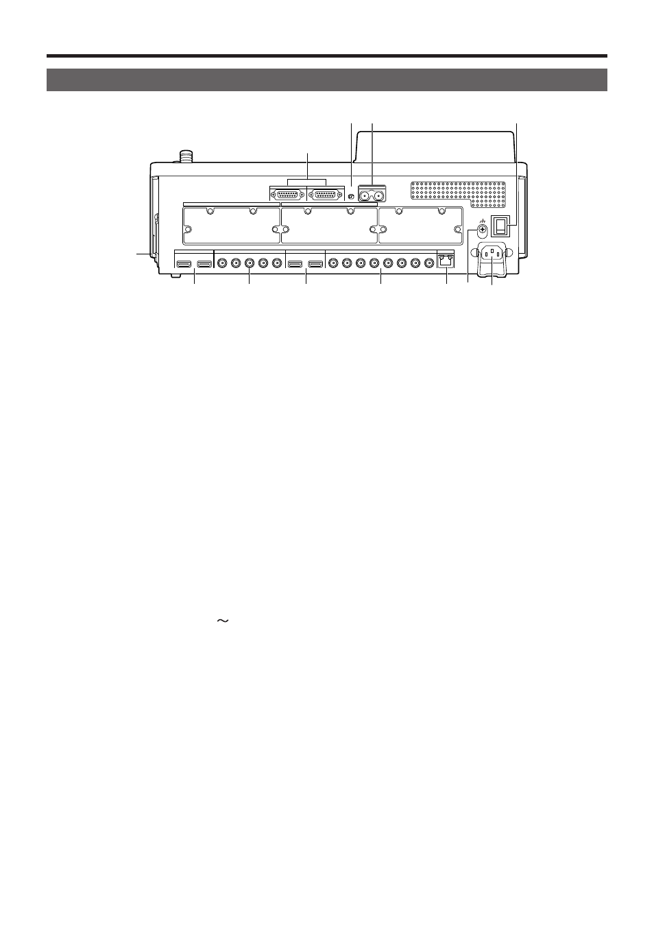
Rear panel area
TALLY/GPI 1
EXPANTION SLOT A
EXPANTION SLOT B
REF
BOOT
SV NM
SIGNAL
GND
POWER
LAN
12G SDI IN
12G SDI OUT
HDMI IN
HDMI IOUT
1
2
3
4
5
1
1
2
2
1
2
3
4
5
6
7
8
AC IN
~
ON
OFF
TALLY/GPI 2
Power switch [POWER]
When the power switch is turned on, the POWER indicator
(
1
) lights up, and the unit can be operated.
HDMI output connectors [HDMI OUT 1, 2]
Connect to external devices with an HDMI cable.
SDI signal output connectors
[12G SDI OUT 1 to 5]
Assignable with menus
HDMI input connectors [HDMI IN 1, 2]
Connect to external devices with an HDMI cable.
SDI signal input connectors [12G SDI IN 1 to 8]
12G SDI IN 1 to 12G SDI IN 4 can use the up-converter
function.
LAN connector [LAN] (RJ-45) (1000Base-TX)
Refer to “External interfaces”.
Ground connector [SIGNAL GND]
Connect to the system’s earth ground.
AC power input socket [AC IN ]
(AC 100 V to 240 V, 50/60 Hz)
Connect one end of the supplied power cable to this socket
and the other end to the AC outlet.
The supplied power cable comes with a 3-pin power plug.
Be absolutely sure to plug it into a 3-point power outlet as
the power source in order to earth the unit securely.
If a 3-point power outlet is not available for this connection,
be absolutely sure to consult your dealer.
Option slot SLOT A [EXPANSION SLOT A]
Option slot SLOT B [EXPANSION SLOT B]
Each of these is an input/output option slot.
A SDI input unit, HDMI output unit or other optional unit
can be installed in these slots.
For details, refer to “How to install the optional units” and
the operating instructions of the unit concerned.
TALLY/GPI input/output connectors
[TALLY/GPI 1, TALLY/GPI 2]
(D-sub 15-pin, female, inch screw)
Refer to “External interfaces”.
BOOT switch [BOOT SV NM]
This switch is used for maintenance purposes.
For normal operations, select the “NM” (normal) position.
Reference input connector/BB output connector
[REF]
Loop-through output in the external sync mode.
If the loop-through output is not going to be used, provide
a 75-ohm termination.
BB signals output from both connectors in the internal sync
mode.
Cooling fan