Video interface, Video interface -16 – Altera DisplayPort MegaCore Function User Manual
Page 52
Bit
Comments
7:0
Lane 0 symbol n
When data is received, data is produced on lane 0, lanes 0 and 1, or on all four lanes according to how
many lanes are currently used and link trained on the main link. The IP core provides the data output
immediately after the data passes through the descrambler and features all control symbols, data, and
original timing. As data is always valid at each and every clock cycle, the
rxN_stream_valid
signal
remains asserted.
Video Interface
This interface (
rxN_video_out
) allows access to the video data as a non-Avalon-ST stream. You can use
this stream to interface with an external pixel clock recovery function. The stream provides synchroniza‐
tion pulses at the start and end of active lines, and at the start and end of active frames.
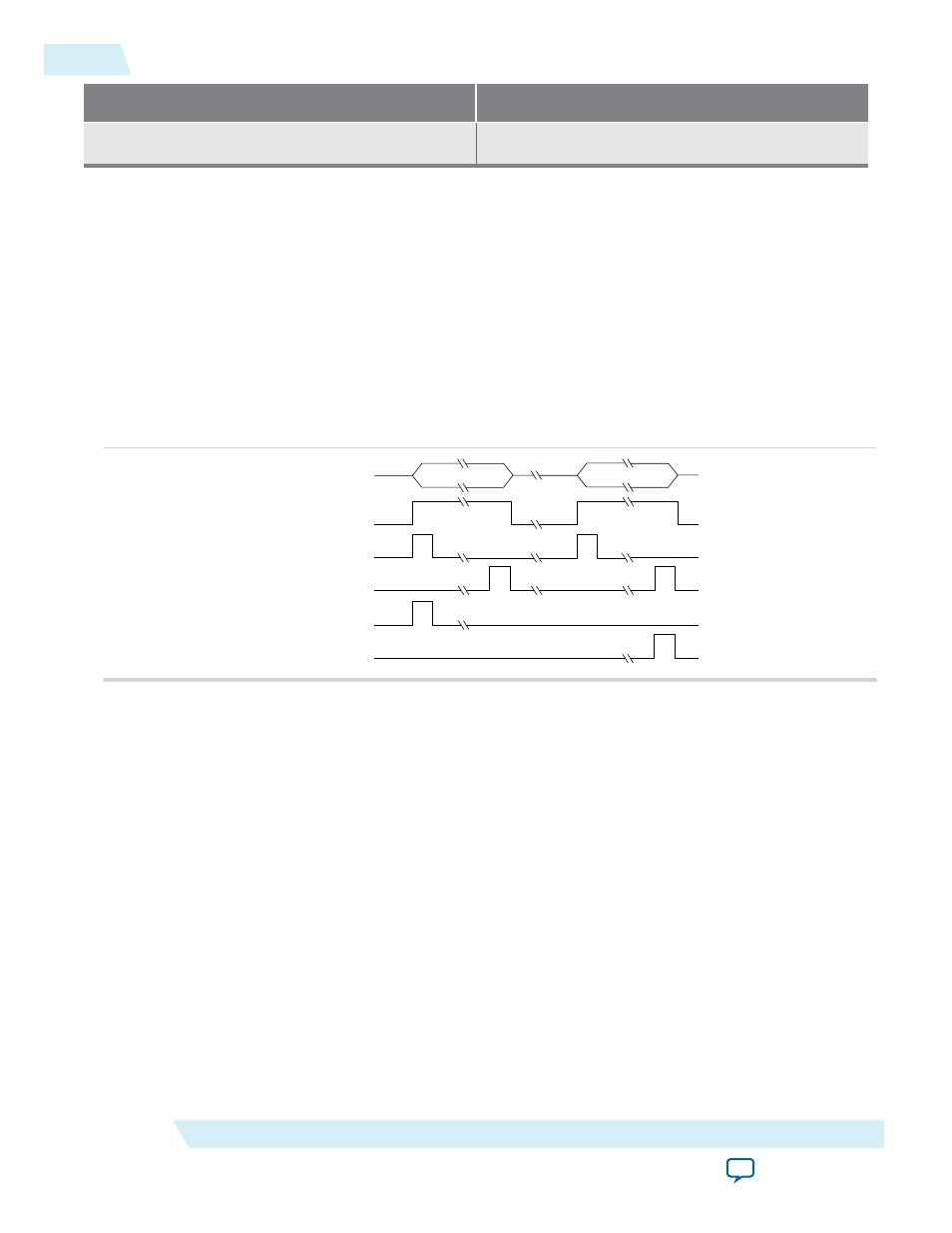
Figure 5-4: Video Out Image Port Timing Diagram
Line[0]
Line[n]
rxN_vid_data
rxN_vid_valid
rxN_vid_sol
rxN_vid_eol
rxN_vid_sof
rxN_vid_eof
The
rxN_vid_overflow
signal is always valid, regardless of the logical state of
rxN_vid_valid
.
rxN_vid_overflow
is asserted for at least one clock cycle when the sink core internal video data FIFO
runs into an overflow condition. This condition can occur when the
rxN_vid_clk
frequency is too low to
transport the received video data successfully.
You specify the maximum data color depth in the DisplayPort parameter editor. The same output port
transfers both RGB and YCbCr data in either 4:4:4 or 4:2:2 color format. Data is most-significant bit
aligned and formatted for 4:4:4.
5-16
Video Interface
UG-01131
2015.05.04
Altera Corporation
DisplayPort Sink