Back side – Rugged Cams Premier DVR User Manual
Page 11
10
- -
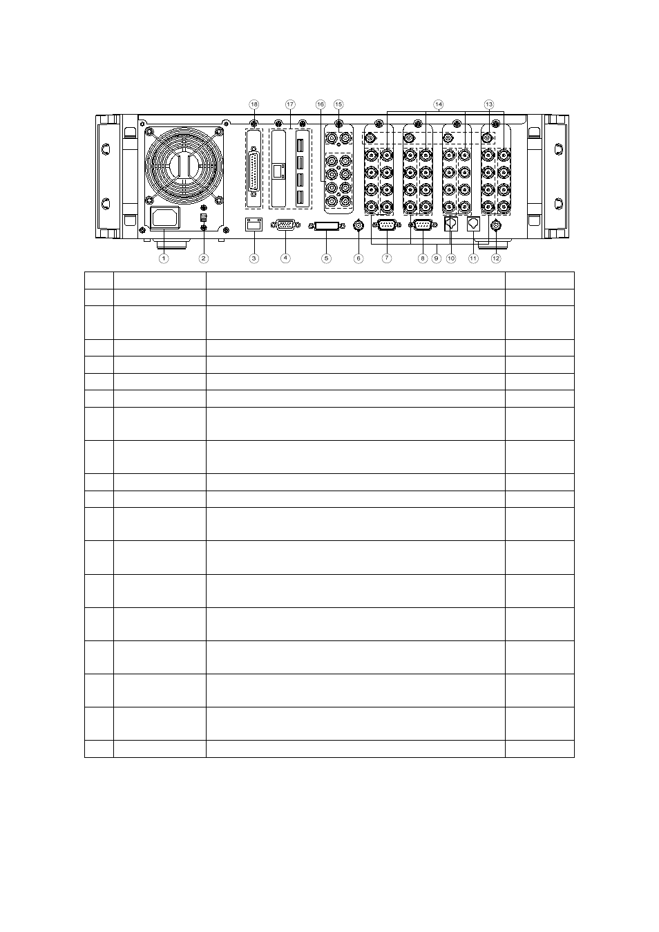
Back side
No Name
Function
Format
1 AC
IN
Connects the product body power cable
2 AC
Selector 110V or 220V voltage selection(DVR does not come with
free Voltage)
3 Ethernet
ADSL, Cable Modem, Ethernet 10/100 Base-T connection
RJ-45
4 VGA
VGA monitor connection
D-SUB 15
5 DVI
Digital monitor connection
DVI-D
6 TV
CCTV monitor connection
BNC
7 PSTN
PSTN/ISDN modem connection(RS-232C) D-
SUB9PIN
8 RS-232C
Serial cable connection for the system upgrades
D-
SUB9PIN
9 VIDEO
IN
Video camera connection
BNC
10 RS422
PTZ camera control line connection
RJ-11 6PIN
11 RS485
PTZ camera control line connection
Interacting with POS/ATM/MTRIX
RJ-11 6PIN
12 SPOT
Connection of CCTV monitor that displays a channel image
where an event signal has occured
BNC
13 Quad-Out
Connection of the CCTV monitor for 4-segmentation display
One screen consists of 4 channels
BNC
14 VIDEO
OUT
(loop-back)
Image signal loop-back output connection
BNC
15 AUDIO
OUT Audio output connection(Line Only output) - Option
- 4ch / 8ch / 16ch audio board
RCA
16 AUDIO
IN
Audio input connection - Option
- 4 Line/4 MIC or 8 Lines or 16 Lines
RCA
17 EXT0/EXT1 External backup device connection, USB 2.0(default)
Option - IEEE1394
USB or
Firewire400
18 DIO
Sensor/Relay Extension Board connection - Option
D-SUB 25