Other device connection – Rugged Cams Premier DVR User Manual
Page 13
12
- -
Other device connection
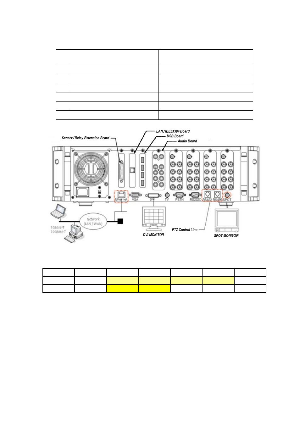
Connect the PTZ control cables, audio input/output, network and sensors, as shown in the following figure.
Connection device
DVR terminal
1
PTZ camera
RS422 or RS485
2
SPOT monitor(CCTV monitor)
BNC
3
DVI monitor
DVI
4
Audio input / Audio output
RCA Audio input / Audio output
5
LAN Cable
Ethernet
6
Sensor/Relay extension board
DIO
(1)PTZ camera
For a PTZ camera, connect the control cable of the PTZ camera to the RS422 or RS485 connector.
Use RJ-11 6PIN Type for the RS422 and RS485, PIN configuration is as follows.
PIN
1 2 3 4 5 6
RS422
GND
T+
T-
R+
R- GND
RS485
GND
TR+
TR- TR+ TR- GND
(2)SPOT monitor
The SPOT monitor is the CCTV monitor in which to see the event occurrence screen.
The SPOT monitor displays images of the channel where an event (motion, sensor or sound) is detected in
the full screen mode. The interval of the event check is one second, the last detected image is displayed in
the full screen mode if events are detected on several channels at the same time.
(3)Audio input/output
The audio card is optional, providing three types of audio channels including 16-channel, 8-channel and 4-
channel.
The 4-channel audio board supports 4 microphone inputs, 4 line inputs and 2 audio outputs. You have to
choose either the line input or microphone input for the 4-channel audio board, and the line input and
microphone input can not be used at the same time once one of them is chosen.