Rugged Cams Premier DVR User Manual
Page 15
14
Connection of external sensors
Connect the output of the external sensor to the input terminal marked S1~S16 and GND of the
sensor/relay extension board.
You don’t have to consider the channel number when connecting each input terminal.
Example - When connecting 3 external sensors,
Connect each sensor input terminal and external sensor as follows.
External sensor
Input terminal
GRD
terminal
Sensor1 S1
GND
Sensor 2
S3
GND
Sensor 3
S6
GND
The type of a sensor is divided into NC (Normal Close) and NO(Normal Open), and
please refer to {5-1-2 Data setup} Æ {(7)Event setup} Æ {(B)SENSOR} for its set up.
NC (Normal Close): It normally stays on the closed mode although it is opened once a
signal is received.
NO (Normal Open): It normally stays on the opened mode although it is closed once a
signal is received.
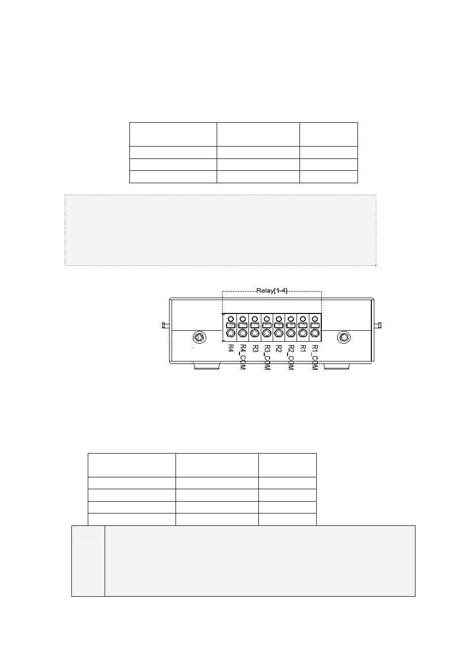
B)Relay connection
Relay output terminal
Give the alarm signal to an external alarm device by connecting the relay output to the external alarm
device such as an alarm light.
Select a terminal from each pair of output terminals marked with Rx_COM and Rx on the output
terminal, and connect it to an external alarm device.
Example - When connecting 4 external alarm devices,
Make connections between relay output terminals and external alarm devices as follows.
External alarm
device
Output terminal
GND
terminal
Relay 1
R1
R1_COM
Relay 2
R2
R2_COM
Relay 3
R3
R3_COM
Relay 4
R4
R4_COM
The type of a relay is divided into NC(Normal Close) and NO(Normal Open), and please
refer to {5-1-2 Data setup} Æ {(8)Alarm Out} Æ {(E)Relay} for its setup.
NC (Normal Close): It normally stays on the closed mode although it is opened once a
signal is received.
NO (Normal Open): It normally stays on the opened mode although it is closed once a
signal is received.