Zilog Z16C35 User Manual
Page 303
Application Note
On-Chip Oscillator Design
15-3
1
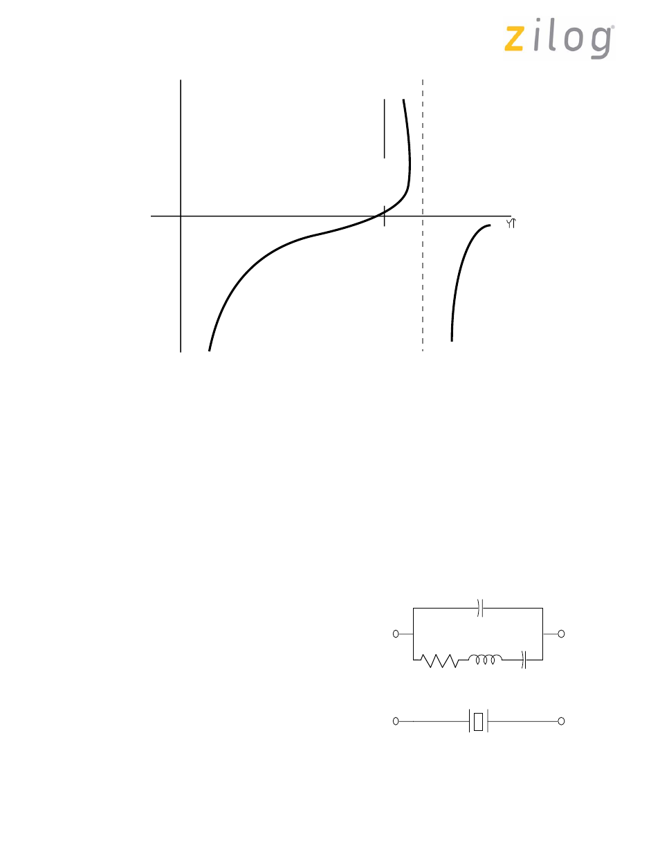
However, there are several ranges of frequencies where
the reactance is positive; these are the fundamental
(desired frequency of operation), and the third and fifth
mechanical overtones (approximately 3 and 5 times the
fundamental frequency). Since the desired frequency
range in this application is always the fundamental, the
overtones must be suppressed. This is done by reducing
the loop gain at these frequencies. Usually, the amplifier’s
gain roll off, in combination with the crystal parasitics and
load capacitors, is sufficient to reduce gain and prevent
oscillation at the overtone frequencies.
The following parameters are for an equivalent circuit of a
quartz crystal (Figure 4):
L
- motional inductance (typ 120 mH @ 4 MHz)
C
- motional capacitance (typ .01 pf @ 4 MHz)
R
- motional resistance (typ 36 ohm @ 4 MHz)
Cs
- shunt capacitance resulting from the sum of the
capacitor formed by the electrodes (with the quartz as a
dielectric) and the parasitics of the contact wires and
holder (typ 3 pf @ 4 MHz).
The series resonant frequency is given by:
Fs
= 1/(2
π
x sqrt of LC),
where Xc and Xl are equal.
Thus, they cancel each other and the crystal is then R
shunted by Cs with zero phase shift.
The parallel resonant frequency is given by:
Fp
= 1/[2
π
x sqrt of L (C Ct/C+Ct)],
where: Ct = C
L
+ C
S
Figure 3. Series vs. Parallel Resonance
0
Region of Parallel
Operation
CAPACITIVE
INDUCTIVE
fs
Z
fp*
* fs - fp is very small (approximately 300 parts per million)
2
Figure 4. Quartz Oscillator
Cs
R
Quartz Equivalent Circuit
L
C
Symbolic Representation
Page 297 of 316
UM011002-0808