Zilog Z16C35 User Manual
Page 304
Application Note
On-Chip Oscillator Design
15-4
OSCILLATOR THEORY OF OPERATION
(Continued)
Series vs. Parallel Resonance.
There is very little
difference between series and parallel resonance
frequencies (Figure 3). A series resonant crystal
(operating at zero phase shift) is desired for non-inverting
amplifiers. A parallel resonant crystal (operating at or near
180 degrees of phase shift) is desired for inverting amps.
Figure 3 shows that the difference between these two
operating modes is small. Actually, all crystals have
operating points in both serial and parallel modes. A series
resonant circuit will NOT have load caps C1 and C2. A
data sheet for a crystal designed for series operation does
not have a load cap spec. A parallel resonant crystal data
sheet specifies a load cap value which is the series
combination of C1 and C2. For this App Note discussion,
since all the circuits of interest are inverting amplifier
based, only the parallel mode of operation is considered.
Ceramic Resonators
Ceramic resonators are similar to quartz crystals, but are
used where frequency stability is less critical and low cost
is desired. They operate on the same basic principle as
quartz crystals as they are piezoelectric devices and have
a similar equivalent circuit. The frequency tolerance is
wider (0.3 to 3%), but the ceramic costs less than quartz.
Figure 5 shows reactance vs. frequency and Figure 6
shows the equivalent circuit.
Typical values of parameters are L = .092 mH, C = 4.6 pf,
R = 7 ohms and Cs = 40 pf, all at 8 MHz. Generally,
ceramic resonators tend to start up faster but have looser
frequency tolerance than quartz. This means that external
circuit parameters are more critical with resonators.
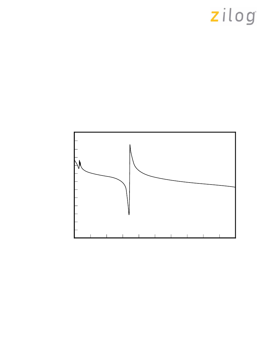
Figure 5. Ceramic Resonator Reactance
0
1
10
100
1000
Impedance
(Ohm
Frequency (KHz)
10000
100000
2000
6000
4000
8000
10000
Page 298 of 316
UM011002-0808