2 read registers, scc cell, Read registers, scc cell – Zilog Z16C35 User Manual
Page 93
ISCC
User Manual
UM011002-0808
87
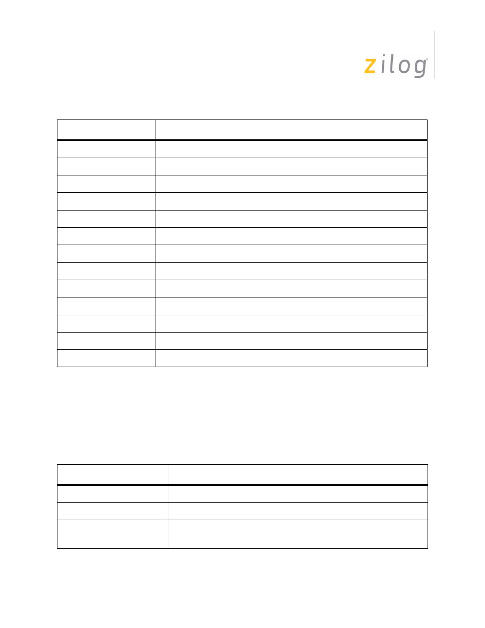
5.2.2 Read Registers, SCC Cell
Four read registers indicate status information, two are for baud rate generation, and one
for the receive buffer. In addition, there are two read registers which are shared by both
channels: one for the interrupt pending bits and one for interrupt vector. See Table 5-2 for
a summary on the SCC cell read registers.
WR3
Receive parameters and control modes
WR4
Transmit and Receive modes and parameters
WR5
Transmit parameters and control modes
WR6
Sync Character or SDLC address
WR7
Sync Character or SDLC flag
WR8
Transmit buffer
WR9
Master Interrupt control and reset commands
WR10
Misc. transmit and receive control bits
WR11
Clock mode controls for receive and transmit
WR12
Lower byte of baud rate generator
WR13
Upper byte of baud rate generator
WR14
Miscellaneous control bits
WR15
External status interrupt enable control
Table 5–24. SCC Cell Read Registers
Register
Description
RR0
Transmit and Receive buffer status and external status
RR1
Special Receive Condition status
RR2
Modified interrupt vector (Channel B only), Unmodified interrupt
vector (Channel A only)
Table 5–23. SCC Cell Write Registers (Continued)
Register
Description
Page 87 of 316