Iscc user manual – Zilog Z16C35 User Manual
Page 66
ISCC
User Manual
UM011002-0808
60
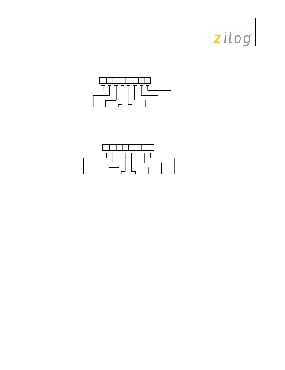
Figure 4–20. sync Character Programming
For those applications requiring any other sync character length, the ISCC makes provi-
sion for an external circuit to provide a character synchronization signal on the /SYNC
pin. This mode is selected by setting bits D5 and D4 of WR4 to “1”. In this mode the
Sync/Hunt bit in RR0 reports the state of the /SYNC pin but the receiver must still be
placed in Hunt mode when the external logic is searching for a sync character match.
When the receiver is in Hunt mode and the /SYNC pin is driven Low, two receive clock
cycles after the last bit of the sync character is received, character assembly will begin on
the rising edge of the receive clock immediately preceding the activation of /SYNC.
D6
D7
D5 D4 D3 D2 D1 D0
Sync7
Sync1
Sync7
Sync3
ADR7
ADR7
Sync6
Sync0
Sync6
Sync2
ADR6
ADR6
Sync5
Sync5
Sync5
Sync1
ADR5
ADR5
Sync4
Sync4
Sync4
Sync0
ADR4
ADR4
Sync3
Sync3
Sync3
1
ADR3
x
Sync2
Sync2
Sync2
1
ADR2
x
Sync1
Sync1
Sync1
1
ADR1
x
Sync0
Sync0
Sync0
1
ADR0
x
Monosync, 8 Bits
Monosync, 6 Bits
Bisync, 16 Bits
Bisync, 12 Bits
SDLC
SDLC (Address Range)
Write Register 6
D6
D7
D5 D4 D3 D2 D1 D0
Sync7
Sync5
Sync15
Sync11
0
Sync6
Sync4
Sync14
Sync10
1
Sync5
Sync3
Sync13
Sync9
1
Sync4
Sync2
Sync12
Sync8
1
Sync3
Sync1
Sync11
Sync7
1
Sync2
Sync0
Sync10
Sync6
1
Sync1
x
Sync9
Sync5
1
Sync0
x
Sync8
Sync4
0
Monosync, 8 Bits
Monosync, 6 Bits
Bisync, 16 Bits
Bisync, 12 Bits
SDLC
Write Register 7
Page 60 of 316