2 rear panel – Comtech EF Data CDD-562L User Manual
Page 33
CDD-562L/564 Demodulator with IP Module
Revision 2
Introduction
MN/CDD564L.IOM
1–9
1.3.5.2 Rear Panel
Chapter 3. REAR PANEL CONNECTORS
AND
PINOUTS
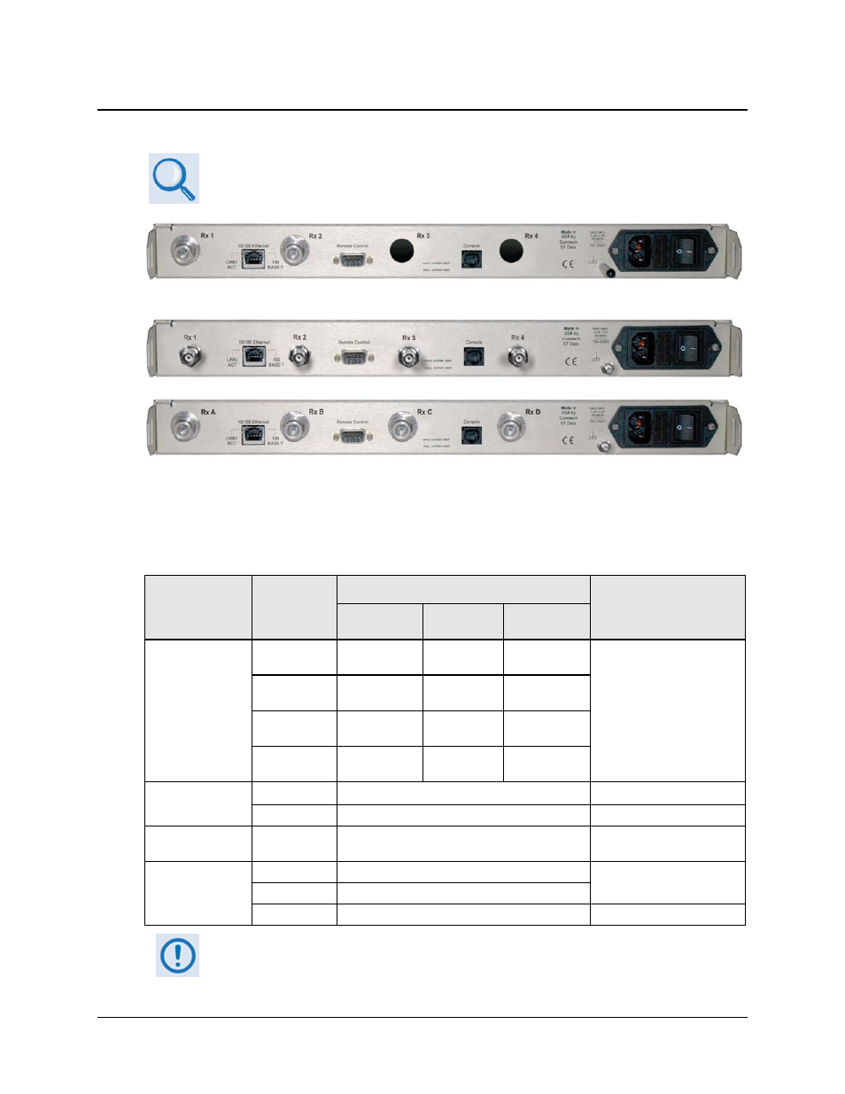
Figure 1-7. Rear Panel Views
Figure 1-7 shows the rear panels of the demodulators. External cables are attached to connectors on
the rear panel of the unit, comprised as follows:
Connector Group
(Chapter 3 Sect.
Ref.)
Name
Connector Type
Function
CDD-562L
(L-Band)
CDD-564
(70/140 MHz)
CDD-564L
(L-Band)
IF
(Sect. 3.2)
Rx 1 (Rx A on
CDD-564L)
Type ’N’ female
BNC female
Type ’N’ female
IF Input
Rx 2 (Rx B on
CDD-564L)
Type ’N’ female
BNC female
Type ’N’ female
Rx 3 (Rx C on
CDD-564L)
N/A
BNC female
Type ’N’ female
Rx 4 (Rx D on
CDD-564L)
N/A
BNC female
Type ’N’ female
Terrestrial Data
(Sect. 3.3)
10/100 Ethernet RJ-45 female
Ethernet Traffic
Console RJ-11 female
Async Serial Console Port
Utility
(Sect. 3.4)
Remote Control 9-pin Type ‘D’ male
Remote Interface (EIA-232) for
Factory Test
Power/Ground
(Sect 3.5)
AC
See Sect. 3.5.1
Chassis power
DC (Optional)
See Sect. 3.5.2
Ground #10-32
stud
Common Chassis Ground
The European EMC Directive (EN55022, EN50082-1) requires using properly
shielded cables for DATA I/O. These cables must be double-shielded from end-
to-end, ensuring a continuous ground shield.
CDD-562L
CDD-564
CDD-564L