1 rx if connections, 1 cdd-562l and cdd-564l l-band chassis rx input, 2 cdd-564 70/140 mhz chassis rx input – Comtech EF Data CDD-562L User Manual
Page 49
CDD-562L/564 Demodulator with IP Module
Revision 2
Rear Panel Connections
MN/CDD564L.IOM
3–3
3.2.1
Rx IF Connections
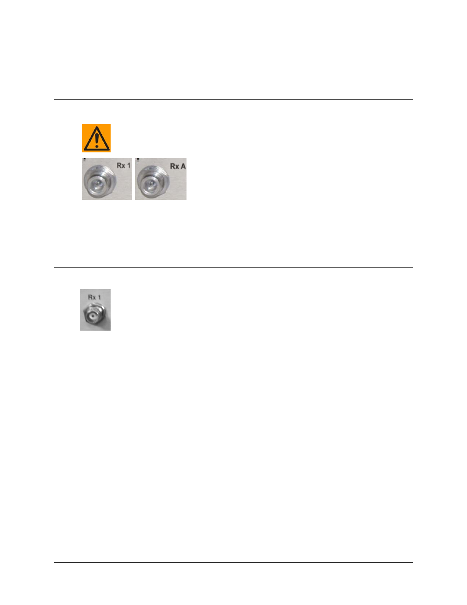
3.2.1.1 CDD-562L and CDD-564L L-Band Chassis Rx Input
There may be DC voltages present on the Type ‘N’ Rx IF connectors, up to a
maximum of 48 volts.
The Rx IF input port connectors on the L-Band demodulators are
50
Ω ‘N’ female types. Two connectors, labeled Rx1 and Rx2,
are provided on the CDD-562L (shown at left), while four
connectors labeled Rx A through Rx D are available on the
CDD-564L (shown to the right).
The return loss on these ports is typically better than 17 dB, and if the user wishes to connect to a
75
Ω system, an inexpensive ‘N’ to ‘F’ type adapter can be used and is available as an optional
accessory. While there will be a reduction in return loss when doing this, the effect in most
systems will be imperceptible.
3.2.1.2 CDD-564 70/140 MHz Chassis Rx Input
The Rx IF Input port connectors are BNC female types, with a programmable
impedance of 50
Ω or 75Ω. Four connectors, labeled Rx 1 through Rx 4, are provided
on the CDD-564.