2 getting started, 1 equipment list, 2 basic equipment setup – Comtech EF Data CDD-562L User Manual
Page 94
CDD-562L/564 Demodulator with IP Module
Revision 2
Quick Start Guide
MN/CDD564L.IOM
7–2
7.2
Getting Started
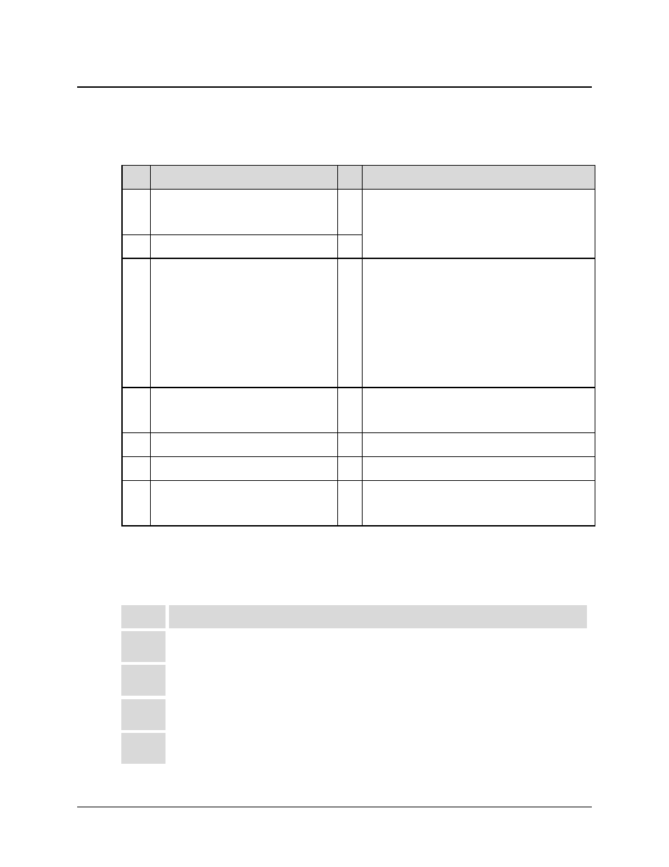
7.2.1 Equipment List
Item Description
Qty Comments
1
CDM-IP modems (e.g., CDM-IP550,
CDM-IP300L, CDM-570/570L w/IP
Module, etc.)
2 Depending upon the modems used, the user may
need to provide equipment to convert 70 MHz IF to
L-Band for a duplex connection.
2 CDD564/564L/562L Demodulator
1
3 10/100 BaseT Ethernet Hub
2
Provided by user. Note the following:
1. Only 10 BaseT operation is supported in
Managed Switch Mode (formerly
easyConnect
™ Mode).
2. RJ-45 crossover Ethernet cables can be
substituted to directly connect PC to CDM-IP
modem without the use of a hub.
4
PC equipped with network interface card
and terminal emulation program (e.g.,
HyperTerminal, Tera Term, etc.)
2 Provided
by
user.
5 Console cable (DB-9 to RJ-11)
1 Supplied by Comtech EF Data.
6 CAT5 Ethernet cables
4 Provided by user.
7 IF cables
2
Provided by user to interconnect Tx/Rx between
both CDM-IP modems (Type BNC for 70/140 MHz
operation or Type ‘N’ for L-Band operation).
7.2.2 Basic Equipment Setup
See Figure 7-2 in Sect. 7.3 of this chapter for the diagram of this basic equipment setup.
Step
Task
1
Connect CDM-IP 1 and CDD-56X Demod 3 to PC 1 via the 10/100 BaseT Ethernet Hub 1;
connect CDM-IP 2 to PC 2 via the 10/100 BaseT Ethernet Hub 2
2
Connect the TX IF on CDM-IP 1 to RX IF of CDM-IP 2; connect the Tx IF on CDM-IP 2 to the
RX1 IF of CDD-56X Demod 3 [RX-1 First Demodulator].
3
Connect the DB-9 end of the Console cable to the COM1 or COM2 port of the PC, and the
RJ-11 end to the Console port on the CDM-IP 1 rear panel.
4
Connect CDM-IP 1, CDM-IP 2, and CDD-56X Demod 3 to a suitable power supply and turn
all units ON.