Verifying the configuration, Radio group configuration example, Network requirements – H3C Technologies H3C WX3000E Series Wireless Switches User Manual
Page 534: Configuration procedure
513
Verifying the configuration
•
You can view the power of each AP on the Operation tab you enter by selecting Radio > Calibration
from the navigation tree.
•
When AP 4 joins (the adjacency number becomes 3), the maximum number of neighbors reaches
the upper limit (3 by default), and the AC performs power adjustment after the calibration interval.
You can view the detailed information, such as decrease of the Tx power value, on the History Info
tab you enter by selecting Radio > Calibration from the navigation tree, selecting the Operation tab,
and then selecting History Info.
Radio group configuration example
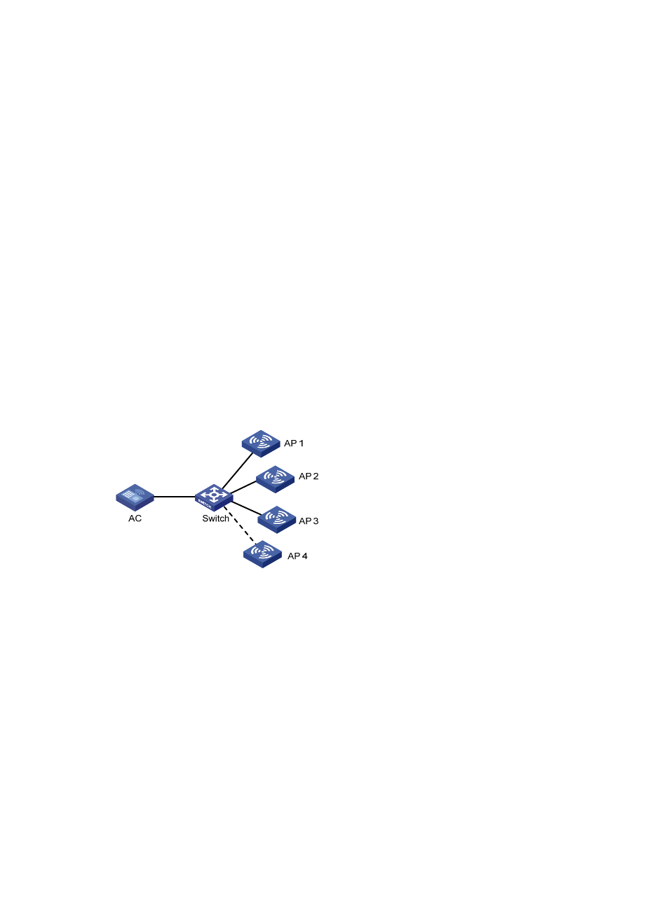
Network requirements
As shown in
, AP 1 through AP 3 are connected to the AC.
•
Configure automatic channel adjustment so that the AC can automatically switch the channel when
the signal quality on a channel is degraded to a certain level.
•
Configure automatic power adjustment so that the AC can automatically adjust the power when the
third neighbor is discovered (or in other words, when AP 4 joins) to avoid interference.
•
Add radio 2 of AP 1 and radio 2 of AP 2 to a radio group to prevent frequent channel or power
adjustments for the radios.
Figure 546 Network diagram
Configuration procedure
1.
Before you configure a radio group, configure AP 1 through AP 4 on the AC to establish a
connection between the AC and each AP.
For the related configuration, see "
."
2.
Configure automatic channel and power adjustment:
a.
Select Radio > Calibration from the navigation tree.
b.
Click the Parameters tab.
c.
Select Auto from the Dynamic Channel Select list, select Auto from the Dynamic Power Select list,
and click Apply.
- H3C WX5500E Series Access Controllers H3C WX3500E Series Access Controllers H3C WX2500E Series Access Controllers H3C WX6000 Series Access Controllers H3C WX5000 Series Access Controllers H3C LSUM3WCMD0 Access Controller Module H3C LSUM1WCME0 Access Controller Module H3C LSRM1WCM2A1 Access Controller Module