Yaskawa i80M Connecting Manual User Manual
Page 105
“
SW1 : System number switch (16-position rotary switch)
SW1 [0] - Normal operation mode
[11 -
Parameter change mode
[4] - Ladder edit mode
NOTE: Positions [2] [3] and [5] through [F] of switch SW1 are for maintenance use only
No one should be allowed to use these switch positions except a qualified YASKAWA service
technician.
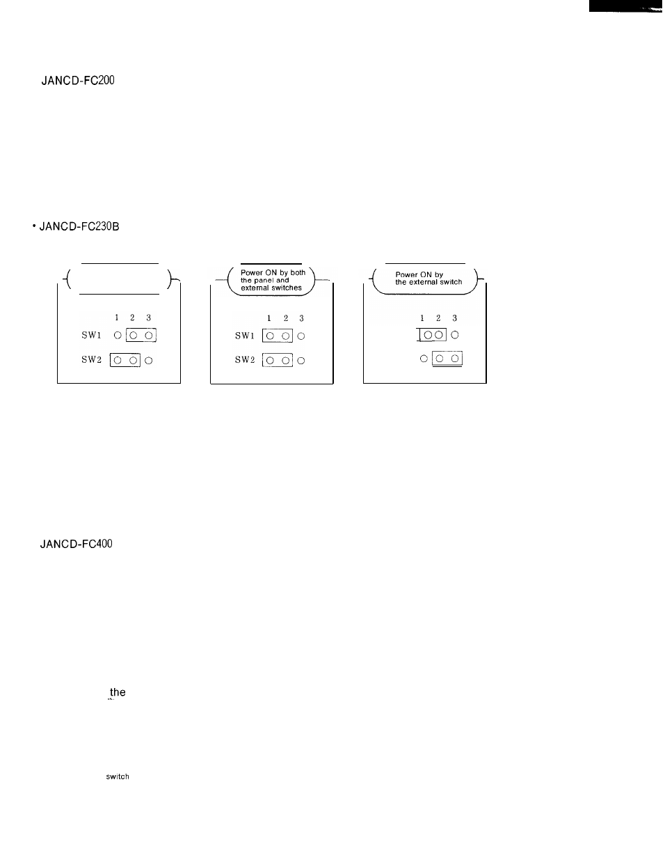
S W 1 , S W 2 : P a n e l / e x t e r n a l s w i t c h O N f u n c t i o n s e l e c t o r s w i t c h
Power ON by
the panel switch
S w l
S W 2
“ JANCD-FC31O-1 (-2)
D/A voltage adjustment trimmers: Factory-adjusted prior to shipment. No further adjust-
ments are needed.
VR1 : First spindle gain adjustment
VR2: First spindle zero adjustment
(VR3: Second spindle gain adjustment)
(VR4: Second spindle zero adjustment)
“
SW1 : System number switch (16-position
SW1 [0] -Normal operation switch
Upon power ON, the system
rotary switch)
starts up synchronized with the NC and im-
mediately executes the application program (index “1 “).
[11
-NC built-in program development mode Upon power ON, the system starts up
synchronized with the NC and displays the application program development
mode screen.
[2] -Standalone execution mode
Upon power ON, the ACGC starts up independently and immediately executes
application program (index “1 “).
[4] -Standalone program development mode
Upon power ON, the ACGC starts up independently and displays the applica-
tion program development mode screen.
NOTE’ Positions [3] and [5] through [F] of switch SW1 are for
maintenance use only. No one should be allowed to use
these
positions except a qualified YASKAWA ser-
vice technician.
105