Yaskawa i80M Connecting Manual User Manual
Page 165
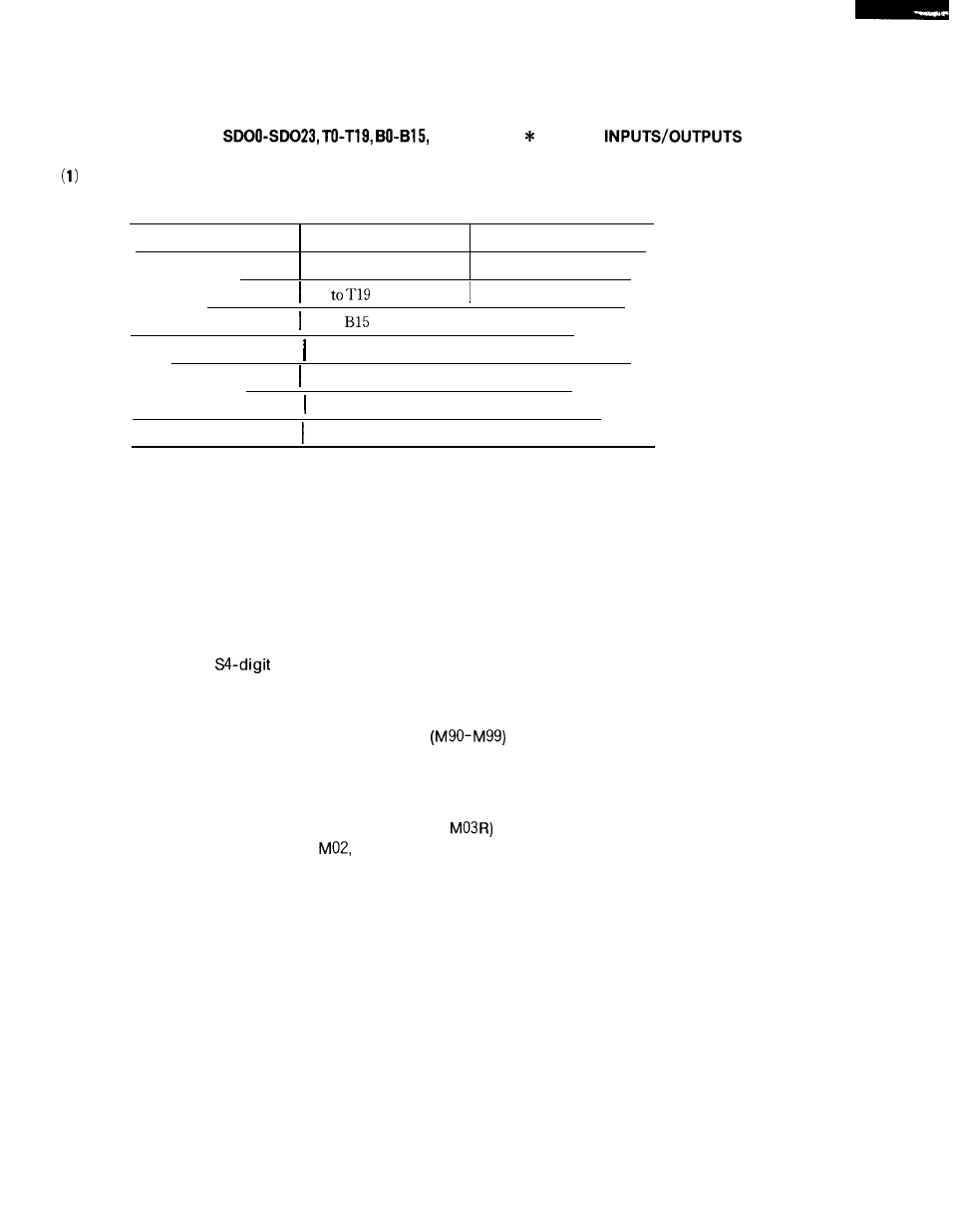
20.2.49 M, S, T AND B CODES
(MAO-MA9,
MF, SF, TF, BF, FIN)
M, S, T and B Codes Output and M, S, T and B Codes Reading Outputs
Table 20.18
M code output
MAO to MA9
# 35200 to # 35211
S code output
SDOO to SD023, S28
# 36540 to # 36567
T code
output
TO
# 3 5 3 0 0 t o # 3 5 3 2 3
B code output
BO to
I
# 3 5 3 3 0 to
# 3 5 3 4 7
M code reading output
MFA
I
#
35350
S code reading output
SF
I
#36517
T code reading output
TF
I
#
35357
B code reading output
BF
I
#
35355
These are outputs for the M, S, T or B command specified by the part program at its execu-
tion in the automatic operation mode.
If any of M, S, T and B command is found at the execu-
tion of the part program in the automatic operation mode, the control outputs it in a BCD or bin-
ary code according to the value that follows the detected command.
Then, after the elapse of the time set in parameter the M, S, T and B code reading outputs
are closed.
NOTE
1.
With the
command, the 12-bit non-contact output or analog
output is provided, disabling the S code output and the S code
reading output.
2. Logic circuit processing M commands
The M code or MFA code outputs are not generated. These com-
mands are the M codes that are processed internally within the
control. Therefore, they cannot be used as the external M codes.
3.
M decoded outputs (MOOR, MO1 R, M02R,
When the MOO, MO1,
or M30 command is executed, decoded
output MOOR, MO1 R, M02R, or M30R is generated accordingly in
addition to the M code and M code reading outputs.
The M decoded output opens when an automatic operation is
started or reset.
When the decoded output M command and move command are
issued for the same block, the M code output is generated at the
beginning of the block, but the decoded output is generated after
completion of move command execution.
A typical M decoded output time chart is presented in Fig. 20.24.
165