Yaskawa i80M Connecting Manual User Manual
Page 327
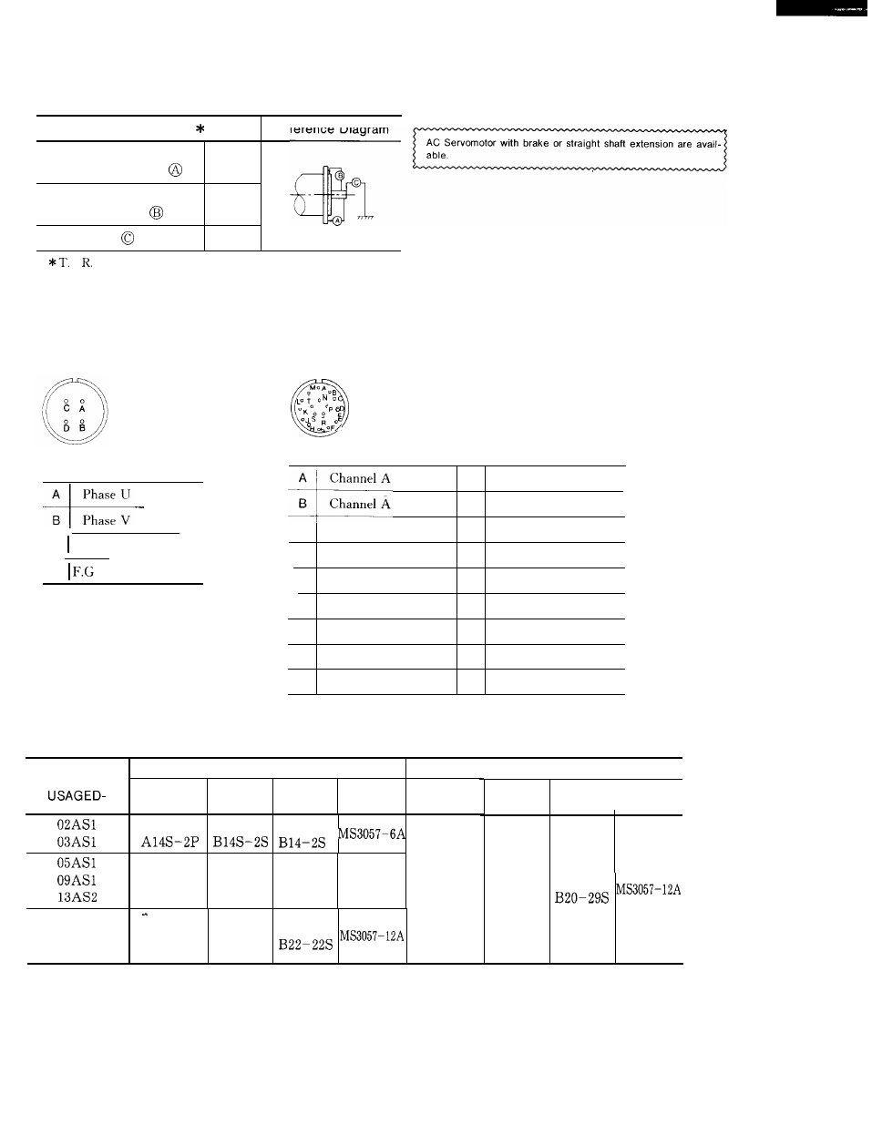
Table A4. 2 Mechanical Specifications in mm
Accuracy
(T. 1. R.)
Reference Diagram
AC
with brake or straight shaft extension are avail-
Flange surface
0.04
able.
perpendicular
to shaft
B
—
c
Flange diameter
0.04
concentric to shaft
A
Shaft run out
0.02
I. (Total Indicator Reading)
Receptacle
Motor
Specifications
Detector
(a) Motor receptacle
A
Phase U
B
Phase V
C Phase W
D
Frame Ground
Connector
.
“P
“ K . .
s
(b) With Brake
A
Channel A output
K
B
Channel A output
L
c
Channel B output
M
D
Channel B output
N
E
Channel Z output
P
F
Channel Z output
R
Reset
G
O v
s
O V (Battery)
H
+ 5VDC
T
+3. 6V (Battery)
J
Frame ground
Motor Connector
Servomotor Type
Receptacle
L-Type
Straight
Cable
Type
Receptacle
Plug
Plug
Clamp
Type
MS3102
MS3108
MS3106
MS3102
MS3108
MS3106
A18–1OP
B18–1OS
B18–1OS
MS3057-1OA
MS3102
A20–29P
20AS2
30AS2
MS3102
MS3108
MS3106
44AS2
A 2 2 - 2 2 P
B22-22S
Encoder Connector
L-Type
Plug
MS3108
B20–29S
Straight
I
Cable
Plug
Clamp
MS3106
327