Yaskawa i80M Connecting Manual User Manual
Page 277
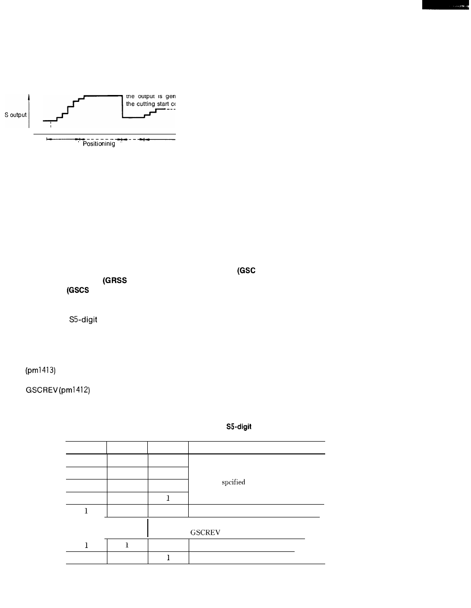
(Typical time chart)
(When the positing command for the block
preceding the cutting command is started,
the output is generated in accordance with
the cutting start coordinates.)
1
,
Cutting command
Execution Cutting command
execution
command
No. 2
execution
No. 1
When parameter pm4011 D4 is set to 1, the constant peripheral speed control can also be exer-
cised for the positioning command. (However, only the spindle rotating speed based on the
positioning end point coordinates is output.)
21. 3.4.2
The above
SPINDLE S COMMAND INPUT (SSTP # 31105), GEAR SHIFT STATE INPUT (GRS
#31107), SPINDLE CONSTANT SPEED INPUT
#31106), GEAR SHIFT STATE
OUTPUT
# 36503), AND SPINDLE CONSTANT SPEED STATE OUTPUT
# 36502)
inputs are used so that outputs other than the part program S command are deli-
vered to the
command analog output.
When the SSTP input is closed, the spindle motor rotaing speed command output based on
the spindle rotating speed specified by the part program is stopped.
If the GRS input is closed in this state, the voltage output defined by parameter GRSREV
is generated.
Further, if the GSC input is closed, the spindle motor rotating speed
command voltage output corresponding to the spindle rotating speed defined by parameter
is generated upon spindle gear range input.
While GRS or GSC based control is exercised, the GRSS or GSCS output is generated.
Table 21.21 SSTP, GRS, and SGC Inputs and
Command Analog
Voltages
SSTP input
GRS input
GSC input
S5-digit command analog voltage
o
0
0
0
0
1
Voltage corresponding to the spindle rotat-
0
1
0
ing speed
by the NC program
o
1
0
0
Ov
I
Voltage
1
corresponding to
o
parameter
1
Parameter GESREV setting
0
Parameter GRSREV setting value
1
1
Ov
NOTE: O: Contact open. 1: Contact closed,
277