Yaskawa i80M Connecting Manual User Manual
Page 169
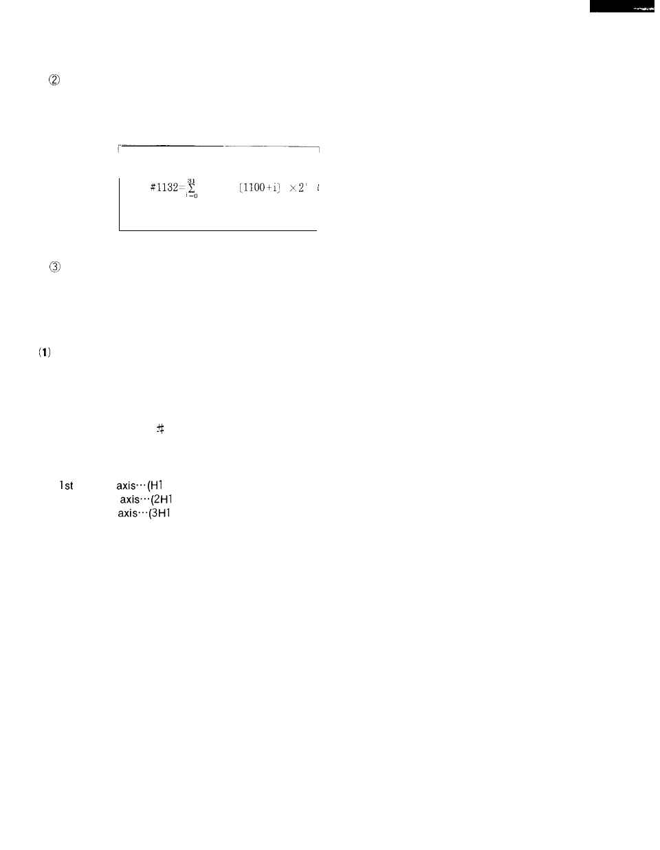
When system variable # 1132 is designated for the left-hand side of an operational ex-
pression, the above-mentioned 32-point output signal (UOO to U031 ) is collectively delivered
out. In this case, a decimal positive value substituted for variable # 1132 is converted to a
binary 32-bit equivalent and then transferred out.
#
I
I
J
When a system variable between # 1100 and # 1132 is designated for the right-hand side
of an operational expression, the ON/OFF state (1. O, 0.0, decimal positive value) of the last
output is read.
20.2.51 MANUAL HANDLE AXIS SELECTION
Manual Handle Feed Axis Selection (HX # 30700 to H5 #30704) Input
When these signals are closed while the manual handle is selected, the corresponding axis can
be fed via manual pulse generator.
When two or more signals are closed, the first selected
axis as viewed from the HX side can be moved.
(2) Manual Simultaneous Three Axes Handle Feed Axis Selection (2HX # 30800 to 2H5 # 30804,
3HX #30810 to 3H5 30814)
These inputs, when closed, specify the maximum three axes for the control provided with
HANDLE dials (manual pulse generator) for simultaneous control of up to three axes.
Handle
to H5)
2nd Handle
to 2H5)
3rd Handle
to 3H5)
NOTE : Selection of Handle axis can be for one axis only.
Superimposition occurs if two or more manual pulse generators are chosen for one axis
20.2.52 MANUAL FEED AXIS DIRECTION SELECTION ( + X # 30710 TO + 5 # 30714,
–X #30720 TO –5 #30724) INPUTS
These inputs specify the motion direction and the axis to be moved when the control is in the
manual jog mode, or manual step feed mode.
Each axis moves when either a plus or minus
direction axis contact is closed. If all the axes are selected, maximum number of simultaneous
controllable axes will work.
When both plus and minus direction contacts for each axis are closed or opened the
selected axis cannot move or decelerate to a stop during motion.
169