Yaskawa i80M Connecting Manual User Manual
Page 140
20.2.24 AUXILIARY FUNCTION LOCK (AFL # 30067) INPUT
This is the input for omitting the M/S/T function in executing part programs in the automatic op-
eration mode.
While the AFL input contact is closed, the control disregards M/S/T instructions of programs
when executing part programs.
However, M code decoded outputs (MOOR, MO1 R, M02R,
are output. Also, the analog D/A output is delivered to the spindle,
When the AFL input contact is closed or opened during the execution of part programs, the
change becomes effective from the block subsequent to the current block.
20.2.25 REFERENCE POINT RETURN CONTROL 1/0 SIGNALS
(ZRN # 30070,
DC5 # 30730-# 30734, ZPX-ZP5 # 36300-# 36304, 2ZPX-1ZP5
# 36310-# 36314, 3
ZPX
-3
ZP
5 # 36320-# 36324, 4zPX-4ZP5 # 36330- #36334)
These are input and output signals for bringing the machine to the machine reference point
upon the energization of the control,
The following reference point return methods are available,
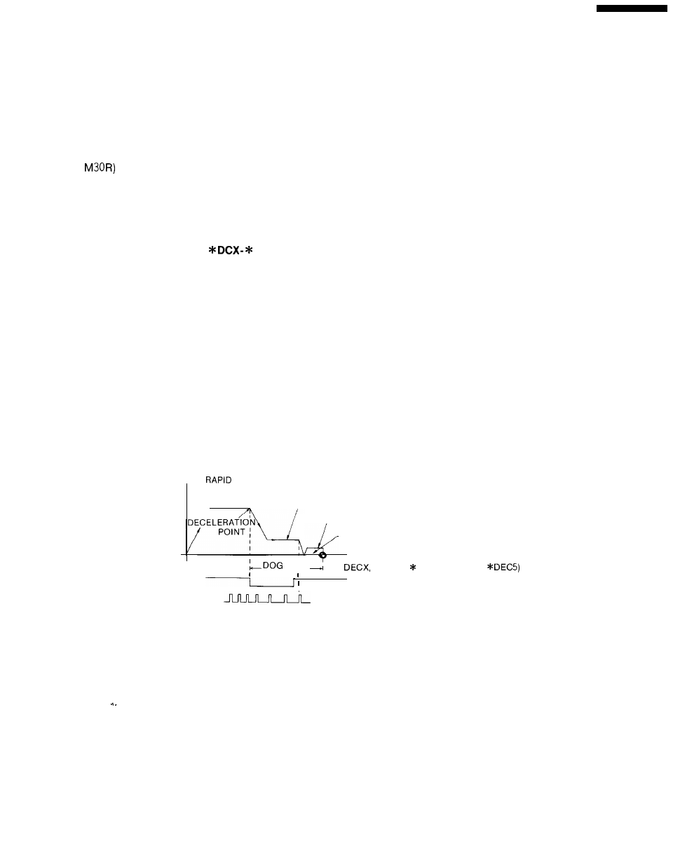
(1) Grid Method
When this method is employed, the reference point is determined according to the position de-
tector zero point pulse (1 pulse/revolution).
When the ZRN input is closed in the manual jog or RPD mode after power ON and then the
axis is moved in the reference return direction, the reference point return operation is per-
formed as indicated in Fig 20.8. (The same applies to the execution of G28 in the automatic op-
eration modes.)
SPEED
TRAVERSE
(Pm 2801 -Pm 2805)
APPROACH SPEED (Pm 2521 -Pm 2525)
/
CREEP SPEED (Pm 2531 -Pm 2535)
TRAVERSE DISTANCE (Pm 4451 -Pm 4455)
SPEED SEQUENCE
WIDTH
(*
* DECY,
DECZ, * DEC4,
SPEED LS SIGNAL
--- ZERO POINT PULSE
Fig. 20.8 Reference Point Return Operation (Grid Method)
140