Yaskawa i80M Connecting Manual User Manual
Page 177
20.2.60 GEAR SHIFT ON (GRO # 31107) INPUT AND SPINDLE ORIENTATION
#31 106)
INPUT
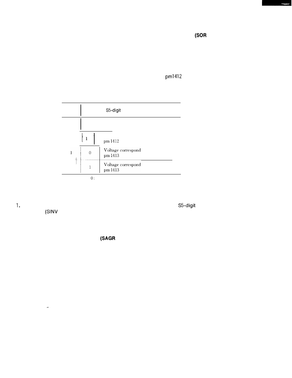
These inputs are used to make the S5-digit command analog output and non-contact output
provide outputs other than the part program S command.
When GRO input is closed, the vol-
tage set by parameter pml 413 is output.
If SOR input is closed, the spindle speed set to parameter
by the spindle gear
range input and spindle motor speed command voltage corresponding to each gear are output.
Table 20.25
GRO
SOR
Input
Input
I
Command Analog Voltage
o
o
I
Voltage corresponding spindle speed
command by NC program.
o
Voltage corresponding to parameter
Voltage corresponding to parameter
---
pm 1413
Voltage corresponding to parameter
1
1
pm 1413
1:
Closed,
open
NOTE
With the analog output in response to the GRO/SOR input and the
analog output
inverted
#31 104) input, it is possible to invert the voltage command for spindle drive.
2. The period of time betweent the setting of GRO and SOR inputs and the catching- up of
the analog voltage value is shorter than 100 ms.
20.2.61 SPINDLE SPEED REACHED
#311 16) INPUT
This input is used to inform, in the case of the S4-digit command, that the spindle speed has
reached the specified value at the start of cutting at the execution of the part program in the
automatic operation mode.
When the positioning command is replaced by the cutting com-
mand, the control initiates a cutting operation after verifying that the SAGR input is closed.
1 7 7