Yaskawa i80M Connecting Manual User Manual
Page 26
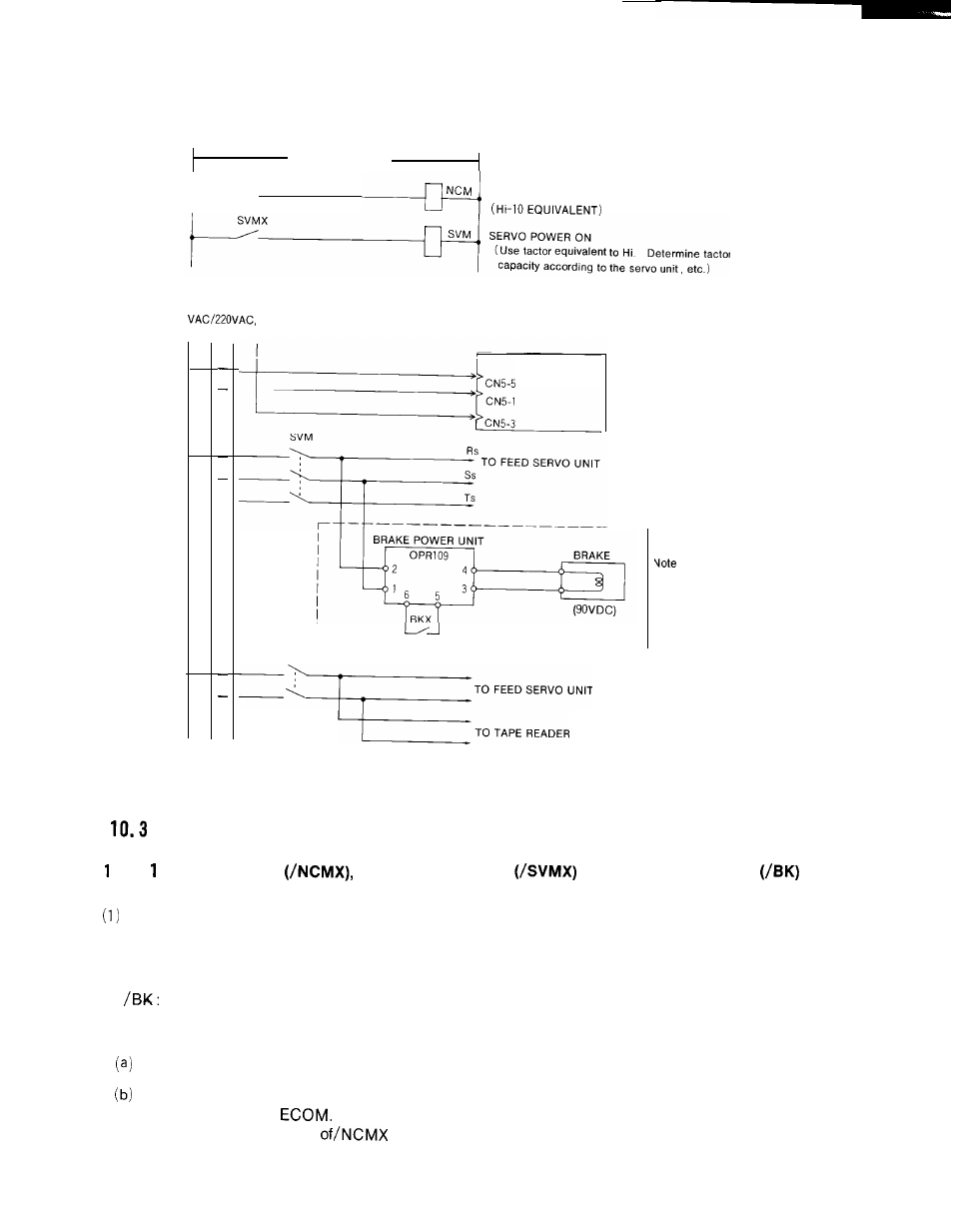
The connection example of the main circuit is shown below.
10OVAC OR 200VAC
i--’
NCMX
NC POWER ON
200
50/60Hz
R
S
T
E
C p s
L––––––––––––_––– __– ___
NCM
: Required only for using
holding brake.
The brake is built in the
motor.
Fig. 10.3
DETAILS OF SIGNALS
().3.
NC POWER ON
SERVO POWER ON
AND BRAKE RELEASE
OUTPUT
/NCMX: This output is turned on when the logic circuit of the control is energized.
(2) /SVMX: This output is turned on when the servo unit is energized. With an external servo
unit, turn on the power supply when this signal is output,
(3)
Output to release the retaining brake of the feed axis.
(4)
The power supply turning on sequence is as follows:
Close the power supply main switch for the control
Either depress the POWER ON button on the NC operator’s station, or close the circuit
between EON and
Then, the logic circuit and the servo control circuit are both
energized, and the output
signals (NC power input and output) is activated.
2 6