Yaskawa i80M Connecting Manual User Manual
Page 143
5. If the designated F speed is higher than the F1 -alight maximum speed parameter value
(Pm2865, 2866) while the F1 -digit selector signal is used, the speed is clamped to that para-
meter value.
If the -digit maximum speed setting parameter value is above the regular
maximum cutting speed, the speed is clamped to the regular maximum cutting speed.
20.2.29 SYSTEM NUMBER SETTING MONITOR OUTPUT (SSWSO # 35060 -SSWS3 # 35063)
This output is delivered to the l/O to indicate the setting parameter # 109 state
Note, however, that setting parameter # 109 takes effect only when the FC200 circuit board rot-
ary switch is set to O.
20.2.30 EXTERNAL DATA INPUT (EDO # 30300 THROUGH ED31 # 30337, EDSAO # 30344
THROUGH EDSA2 # 30346, EDCL, EREND AND
These inputs/outputs are used to make the machine perform the following functions by ex-
ternal inputs:
External inputting of 4-digit program (1 to 99999
selects the work number desired.
(b)
External tool compensation input.
These external input signals can command compensation values for tool length and dia-
meter.
(c) External work coordinate system shift.
The work coordinate system shift value can be entered externally.
Externally entered axis correction value is added to the shift value of the specified
axis programmed by G54 to G59 and the result is stored as a new shift value.
(2) Input/Output Signals For Inputting External Data
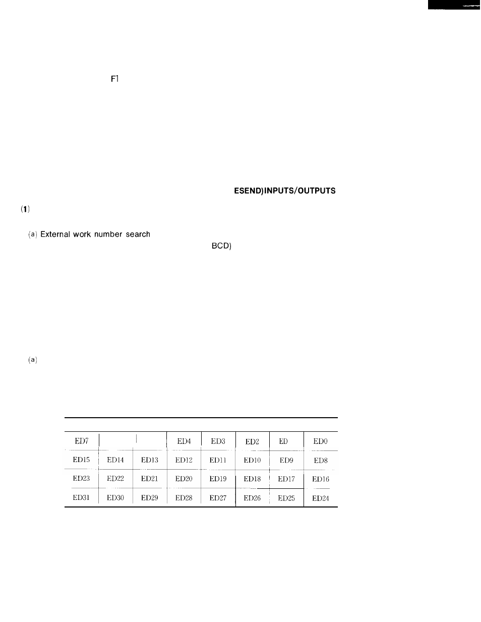
External data inputs (EDO #30300 to ED31 #30337)
These inputs are used for work No. input signal, offset amout input signal and work coordi-
nate system shift signal.
Table 20.6 External Data Input Signal
External Data Input Signal
1
ED6
ED5
1
143