Yaskawa i80M Connecting Manual User Manual
Page 176
(Supplementary Explanation)
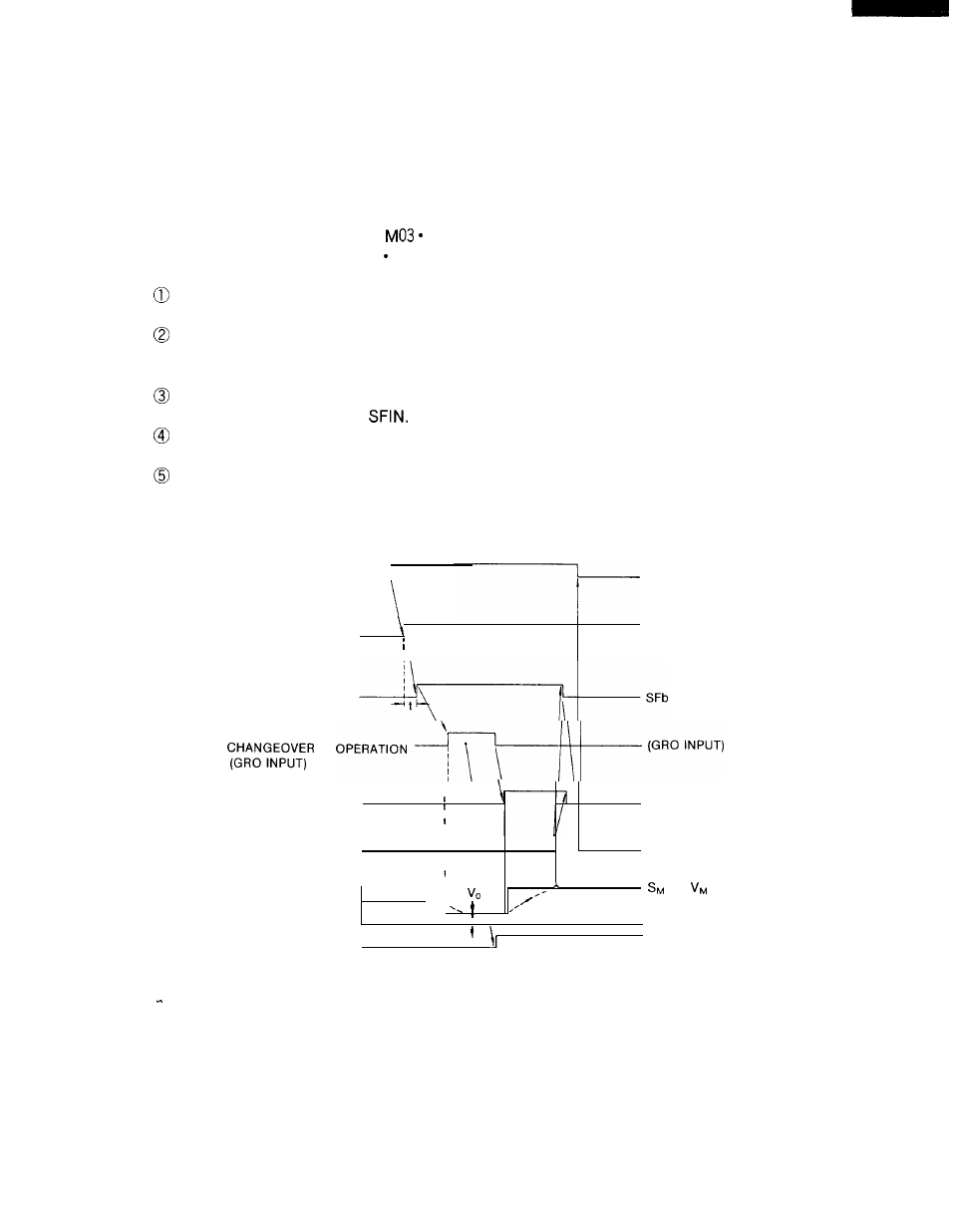
Example) Timing between S command and output
The typical signal exchange timing diagram presented below applies to cases where the
system checks the necessity for gear ratio changeover when a new S command is read,
and automatically effects necessary gear ratio changeover to obtain the spindle revolving
speed specified by the command.
Let us suppose that “S1 000
● ●
gear ratio 2“ has been designated for the preceding
block and that the “S2000;
● ●
gear ratio = GR3° speed range is newly designated.
In this situation:
The control concludes that switching to the GR3 is necessary, and then generates the
GR3S output.
With read command SF which is delayed by time t, read the GR3S and effect machine
side gear ratio changeover.
If the spindle motor needs to be rotated for gear ratio
changeover, turn ON the GRO.
When switching to a gear ratio of GR3 is completed, turn ON the GR3 input and then S
command completion input
When the SFIN rises to the ON state, a new S value output is computed and gener-
ated.
When the spindle speed coincides with the specified speed (S20000), turn ON the FIN.
S COMMAND
CHANGE BLOCK
SPINDLE GEAR
GRIS-GR4S
R A T I D D E S I G N A T I O N
OUTPUT
READ COMMAND
GEAR RATlO
S COMMAND
1
COMPLETION INPUT
\
\
SFIN
MST
1
COMPLETION INPUT
I
FIN
I
1
OR
DA OUTPUT
I
SPINDLE GEAR
GR3
RATlO INPUT
176
Fig. 20.32 Timing between S Command and output