Yaskawa i80M Connecting Manual User Manual
Page 284
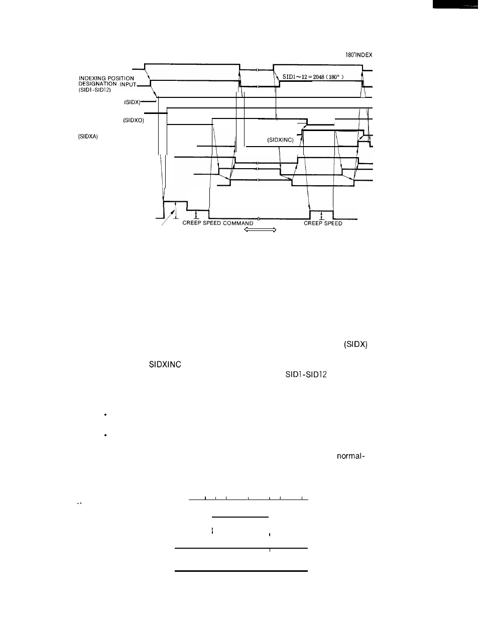
M CODE FOR SPINDLE
M CODE FOR UNCLAMPING,
INDEXING AND CLAMPING
INCREMENTING, AND CLAMPING
SPINDLE INDEXING
REQUEST INPUT
SPINDLE INDEXING
FUNCTION EXECUTION
STATE OUTPUT
SPINDLE INDEXING
INDEXING POSITION
COMPLETION OUTPUT
-
.
,
:
DESIGNATION
INCREMENTAL
M FUNCTION EXECUTION
INPUT
COMPLETION INPUT (FIN)
SPINDLE ROTATION SIGNAL
I
(EXTERNAL SEQUENCE
PROCESSING)
MECHANICAL CLAMP SIGNAL
(EXTERNAL SEQUENCE
PROCESSING)
MECHANICAL CLAMP
VERIFICATION SIGNAL
(EXTERNAL SEQUENCE
PROCESSING)
SPINDLE COMMAN D . . . . . . . . . . .
VOLTAGE
CREEP SPEED
INDEXING ROTATING
SPEED COMMAND
NEXT MACHINING
PERFORMED WITHOUT
SPINDLE ROTATION
Fig. 21.23 Spindle Indexing Time Chart
[When clamping the spindle indexing operation
mechanism, conducting machining, and performing
indexing at a position 180” away from the previous in-
dexed position]
NOTE
●
When initiating spindle indexing during spindle reverse, ensure that
the SINV input is ON while the spindle indexing request input
is ON.
“ When the
input is turned ON to perform incremental spindle
indexing with the SINV input turned ON, the
input pro-
vides incrementing in reverse direction.
“ Spindle indexing operations are not performed during interpolation
pulse output generation.
Be sure that the pulse count resulting from the increment command
does not exceed 1024.
Spindle indexing is performed with the phase C pulse (1 pulse/rev)
edge regarded as the reference pulse.
Therefore, if the phase C
pulse has a certain width, the index position obtained from
direction spindle indexing differs by the phase C pulse width from that
obtained from reverse-direction spindle indexing.
PHASE A/PHASE B PULSE
1
1
1
1
P H A S E C P U L S E -
-
1
1
1
NORMAL-DIRECTION
1
1
REFERENCE-PULSE
I
REVERSE-DIRECTION
I
REFERENCE-PULSE
284