Yaskawa i80M Connecting Manual User Manual
Page 276
NOTE
The spindIe motor rotating speed command output calculation for-
mula is given below.
(Spindle rotating speed command) X (1OV )
Spindle gear range determined by the GR1 -GR4 input
?.. The analog output is positive
when the SINV is open or negative
(–) when the SINV is closed.
3. When the spindle S command stop
input closes, a value
other than mentioned above may be output as the spindle motor rotating
speed command. For details see the section on the spindle S com-
mand stop
input.
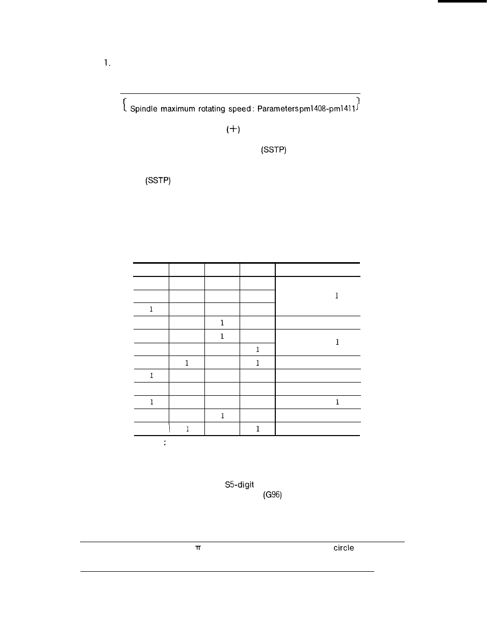
4. As indicated in the table below, the control internally decides on the
spindle gear range depending on whether the GR1 -GR4 inputs are
closed or opened.
Spindle Gear Range Determination
GR1 input GR2 input GR3 input ‘ GR4 input
Control internal range
o
0
0
0
1
1
0
0
Gear range
0
1
0
0
1
0
Gear range 2
1
1
0
1
Gear range
0
0
0
0
Gear range 2
1
0
1
Gear range 1
0
0
1
1
Gear range 3
0
1
1
Gear range
0
1
1
Gear range 2
1
1
Gear range 1
NOTE O: Input Open.
1: Input Closed.
(Supplementary Explanation)
●
Constant peripheral speed control and
command output
When the constant peripheral speed command
is issued during automatic
mode part program execution, the output changes at about 40 ms intervals during
accordance with the following formula.
operation
cutting in
(Peripheral speed specified by the S command)
(Current X-coordinate value) X
(the ratio of the circumference of a
to its diameter)
x
(1
Ov)
Spindle gear range maximum rotating speed determined by the GR1 -GR4 input
276