Gpi/gpo cables installation, 4 gpi/gpo cables installation – Doremi IMS1000 User Manual
Page 71
IMS.OM.002949.DRM
Page 71 of 320
Version 1.7
Doremi Labs
● Take another shielded CAT5 or CAT6 cable and plug the end into the connector labeled
AES-OUT 9-16 (Figure 72).
● Plug the other end of the shielded CAT5 or CAT6 cable into the audio processor.
Note: If the audio processor does not have RJ-45 connectors but has a single DB25 connector,
then you will need to use the RJ-45 to DB25 converter that is provided with the IMS1000 (Figure
73).
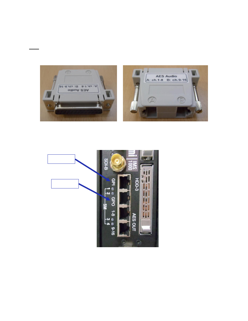
Figure 73: RJ-45 to DB25 Converter
6.4 GPI/GPO Cables Installation
Figure 74: GPI/GPO Connectors
● Plug one shielded CAT5 or CAT6 cable end into the connector labeled GPI on the
IMS1000 board (Figure 74). Install a ferrite core clamp near the connector closest to the
IMS1000. Refer to Section 25 for more information on ferrite core clamp installation.
● Plug the other end of the shielded CAT5 or CAT6 cable into whichever automation
controller is available or required.
GPI
GPO