F.4.1 pc configuration – Comtech EF Data CDM-570 User Manual
Page 431
CDM-570/570L Satellite Modem with Optional IP Module
Revision 12
Appendix F
MN/CDM570L.IOM
F–5
At this point the basic configuration is over and you should be able to:
Step
Task
5
From PC 1: Ping 172.16.10.1 (CDM-IP 1);
Ping 172.16.10.2 (CDM-IP 2);
Ping 172.16.10.12 (PC 2).
6
From PC 2: Ping 172.16.10.2 (CDM-IP 2);
Ping 172.16.10.1 (CDM-IP 1);
Ping 172.16.10.11 (PC 1).
Do not enable IF Loopback (or link the TX to RX by a BNC cable or satellite link) on a
CDM-IP modem operating in Managed Switch Mode when connected to a LAN. In this
configuration, Managed Switch Mode will resend all layer 2 broadcast packets and
cause a “broadcast storm” on the LAN.
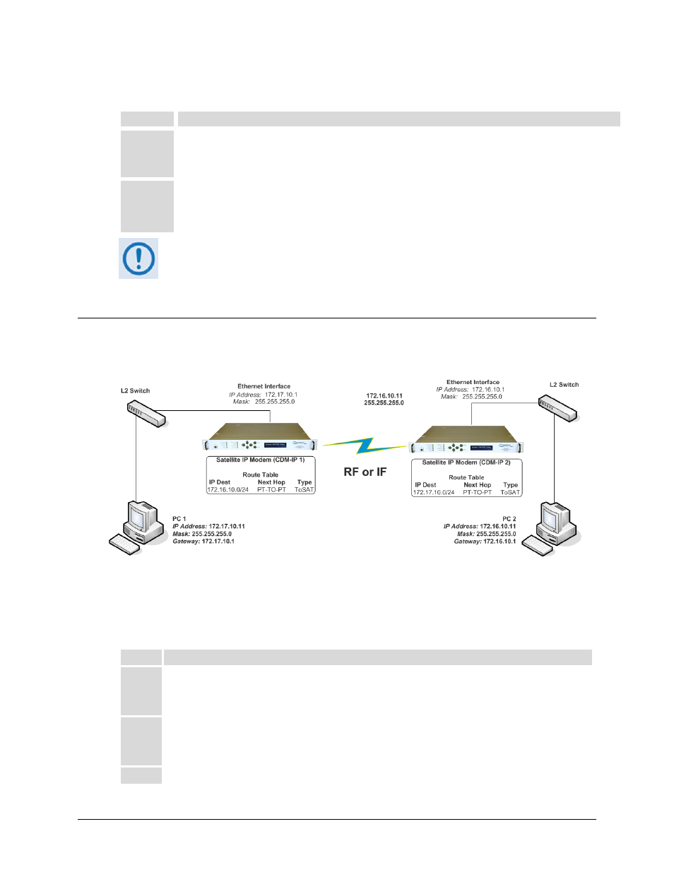
F.4
Router Mode Point-to-Point System Configuration
The procedures outlined in this section will lead to the configuration illustrated in Figure F-3
Figure F-3. Router Mode Point-to-Point System Configuration
F.4.1 PC Configuration
Step
Task
1 PC
1:
Set the IP address to 172.17.10.11;
Set mask to 255.255.255.0;
Set PC Gateway to 172.17.10.1.
2 PC
2:
Set the IP address to 172.16.10.11;
Set mask to 255.255.255.0;
Set PC Gateway to 172.16.10.1.
3
Reboot the PCs (if required).