5 physical features, 1 front panel, 2 rear panel – Comtech EF Data CDM-570 User Manual
Page 45
CDM-570/570L Satellite Modem with Optional IP Module
Revision 12
Introduction
MN/CDM570L.IOM
1–5
1.3.5
Physical Features
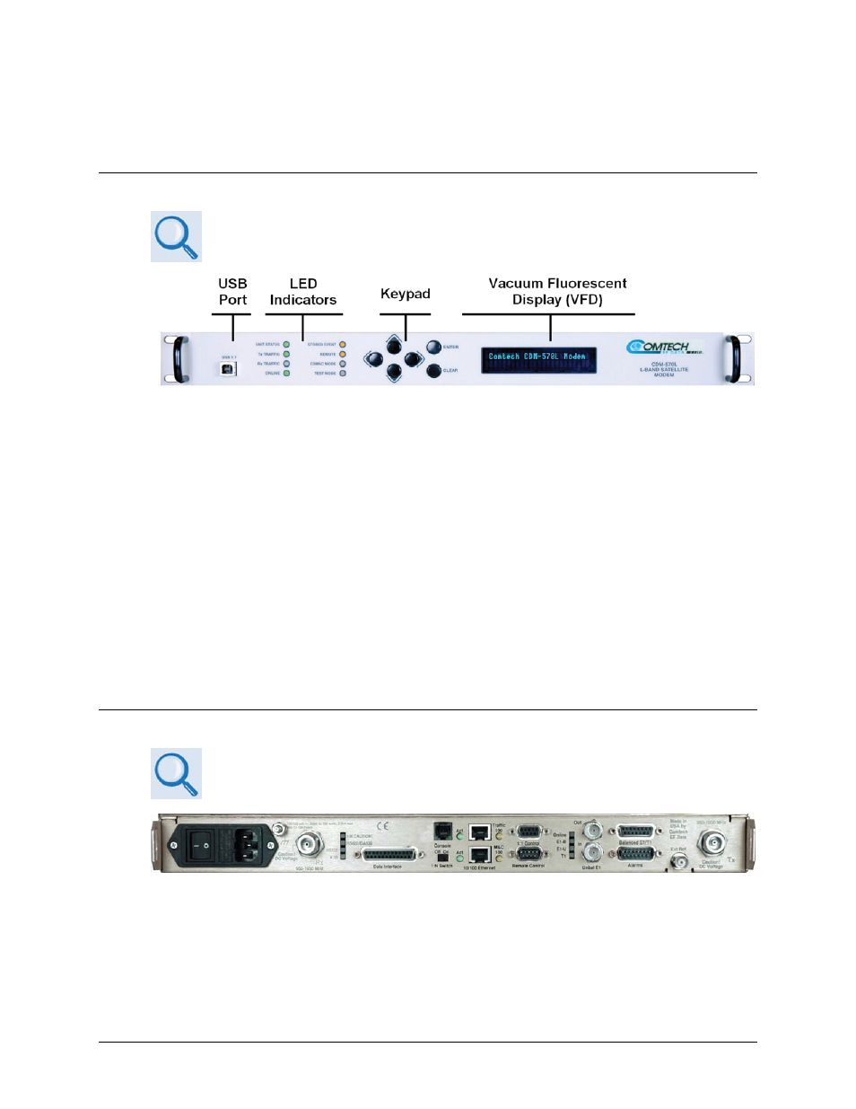
1.3.5.1 Front Panel
The function and behavior of the LED indicators, keypad, and VFD are
described in detail in Chapter 5. FRONT PANEL OPERATION.
Figure 1-3. Front Panel View
(CDM-570L shown)
Figure 1-3 shows the front panel of the CDM-570/570L. The front panel features (from left) a
Type ‘B’ USB connector (reserved for future use with a PC for reflashing the modem firmware);
eight Light-Emitting-Diode (LED) indicators; a keypad; and a Vacuum Fluorescent Display
(VFD):
• The LEDs indicate, in a summary fashion, the status of the unit.
• The keypad comprises six individual keyswitches. The switches provide a positive ‘click’
action for tactile feedback. Data is entered via the keypad, and messages are displayed on
the VFD.
• The VFD is an active display showing two lines of 24 characters each. It produces a blue
light with adjustable brightness. Compared to a Liquid Crystal Display (LCD), the VFD
offers superior viewing characteristics and does not suffer problems of viewing angle or
contrast.
1.3.5.2 Rear Panel
All connectors are described in detail in Chapter 3. REAR PANEL
CONNECTORS
AND
PINOUTS.
Figure 1-4. Rear Panel View
(CDM-570L shown with optional IP Module Ethernet Interface installed)
Figure 1-4 shows the rear panel of the CDM-570/570L. External cables are attached to
connectors provided on the modem rear panel. Refer to Table 1-1 on the next page for a summary
of the available rear panel connectors.