Using the vt mobile, Understanding the controls and indicators, Chapter 3 – Fluke Biomedical VT Mobile User Manual
Page 25: Figure 3-1. controls and indicators
3-1
Chapter 3
Using the VT MOBILE
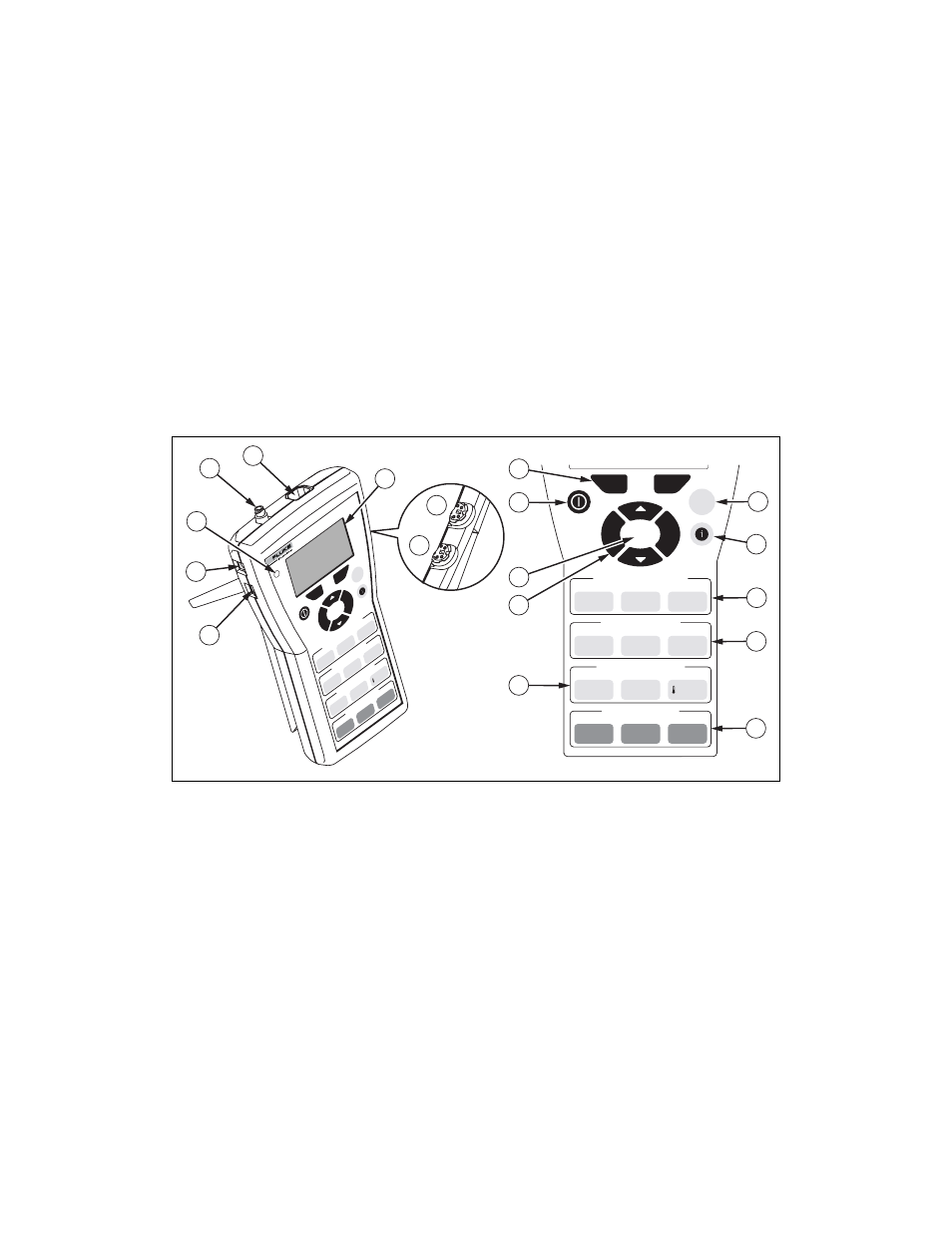
Understanding the Controls and Indicators
Figure 3-1 and Table 3-1 describe the controls and indicators.
F1
F2
Back
ENTER
Setup
Memor
y
Memor
y
VENTILA
TOR P
ARAMETERS
FLO
W/V
OL
FLO
W/
VO
L
TREND
TEST
ZER
O
SENSORS
MORE
PRESSURE
PRESSURE
PRESSURE
TIMING
VOLUME
FLO
W
W
AVEFORM SCREENS
OTHER MEASUREMENTS
SPECIAL FUNCTIONS
%RH
O
2
_ , @
_ , @
11
22
ABC
ABC
55
JKL
JKL
44
GHI
GHI
66
MNO
MNO
88
00
TUV
TUV
77
PQRS
PQRS
99
WXYZ
WXYZ
33
DEF
DEF
GAS FLOW ANALYZER
GAS FLOW ANALYZER
VT MOBILE
VT MOBILE
F1
F2
Back
ENTER
Setup
Memory
Memory
VENTILATOR PARAMETERS
FLOW/VOL
FLOW/VOL
TREND
TEST
ZERO
SENSORS
MORE
PRESSURE
PRESSURE
PRESSURE
TIMING
VOLUME
FLOW
WAVEFORM SCREENS
OTHER MEASUREMENTS
SPECIAL FUNCTIONS
%RH O
2
_
, @
_
, @
11
22
ABC
ABC
55
JKL
JKL
44
GHI
GHI
66
MNO
MNO
88
00
TUV
TUV
77
PQRS
PQRS
99
WXYZ
WXYZ
33
DEF
DEF
9
18
15
16
17
10
11
12
13
14
2
3
4
5
7
8
1
6
ede01f.eps
Figure 3-1. Controls and Indicators