Fluke Biomedical VT Mobile User Manual
Page 46
VT MOBILE
Operators Manual
4-2
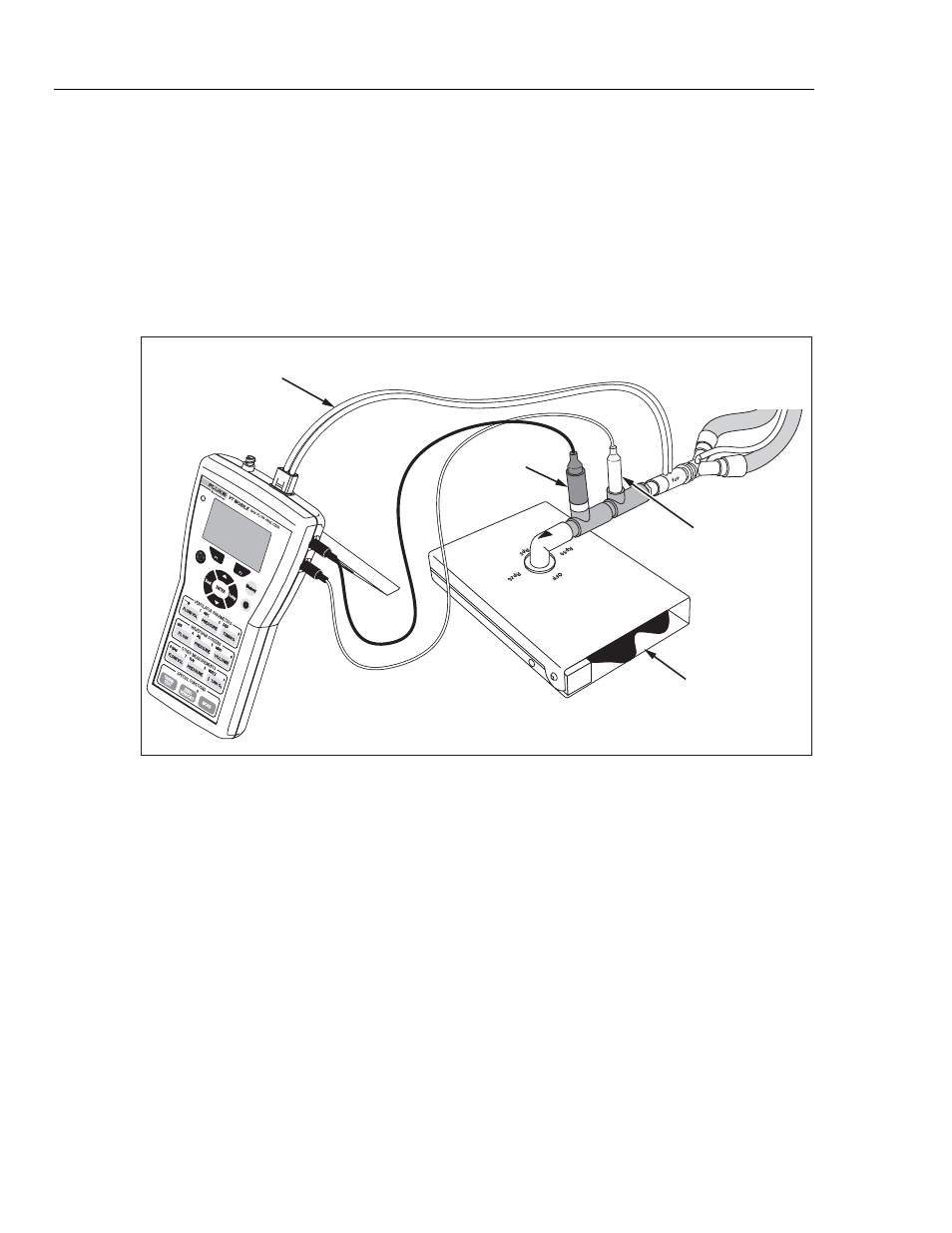
5. Using parts from the Accessory Kit and the connectors provided with the sensors,
make connections between the ventilator and the ACCU LUNG as shown in Figure
4-1. Use the sequence: ventilator Y connector Æ High-Flow Sensor (blue stripe
toward the ACCU LUNG) Æ Temperature/RH Sensor Æ Oxygen Sensor Æ ACCU
LUNG. Vertically align all sensors.
6. Set up the ventilator for a characteristic breath pattern. For example, you could set 10
BPM at 7.5 lpm.
7. Set the ACCU LUNG for C20 compliance (both outer springs engaged) and Rp50
resistance (positioned as shown in Figure 4-1.)
Fluke Biomedical
ACCU LUNG
High Flow Sensor
Oxygen
Sensor
To
Ventilator
Temp./RH Sensor
ede06f.eps
Figure 4-1. Ventilator Connections
8. Apply power to all elements of the test setup. For the Analyzer, press H on, wait for
the Zeroing screen, and then press
G
. The Analyzer is ready to use once the Tidal
Volume screen appears.
9. Press the access keys shown in Table 4-1 to display the various ventilator parameters.
Once you have pressed the first key, you can continue pressing that key to view other
parameters or press
G
to view all the parameters.
10. As described in Table 4-1, the Analyzer calculates 16 breath parameters in Local
Mode. Note that you can view all 16 parameters and other information on one screen
in Remote mode when using the VT for Windows software.
11. Figure 4-2 shows the ventilator parameter screens.
12. Figure 4-3 shows additional oxygen, temperature, relative humidity, and barometric
pressure parameter screens.