Hypertherm HT2000-200 Volt User Manual
Page 151
MAINTENANCE
8-6
HySpeed HT2000
Instruction Manual
19
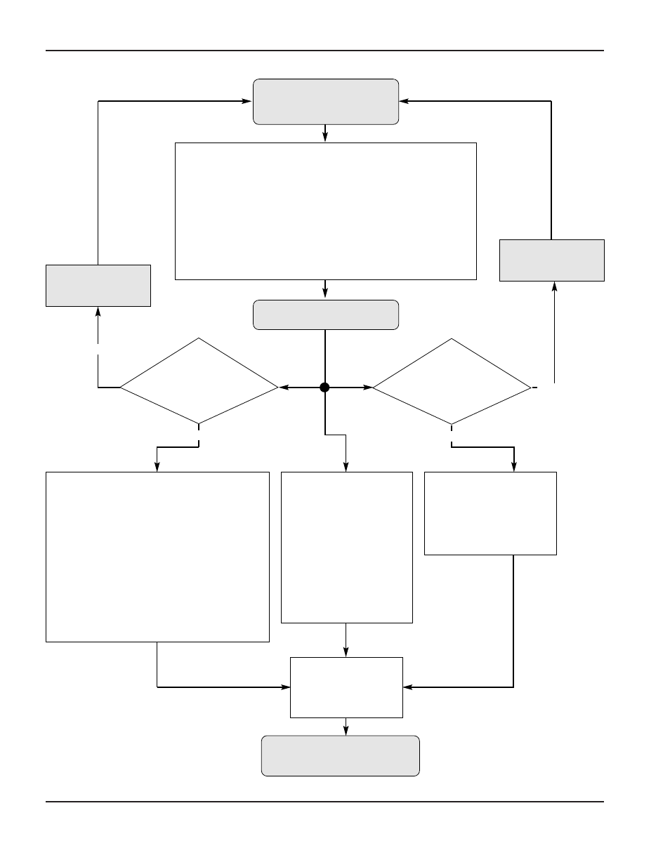
Turn line disconnect
switch on
Push and hold
ON button (PB1)
Release ON button(PB1)
System initialization
is complete
12 VDC to the following interlocks:
1.
S1, S2
(RHF Console door switches)
2.
TSW1
,
TSW2
(Chopper temperature switches)
3.
TS1
(Power Supply transformer temperature switch)
4.
LS1
(Power Supply coolant level switch)
5.
PS3
(RHF Console shield pressure switches)
6.
PS1
,
PS2
(Gas Console plasma pressure switches)
7.
TS2
(Power Supply coolant temperature switch)
8.
FS1
(Power Supply coolant flow switch – note this interlock
will not be satisfied until
M1
coolant pump is activated.)
CR1
(24V/120V relay) on Power Distribution
Board (PCB1) closes.
24VAC to:
LT1
(Power Supply ON light)
PCB2
(Power Supply-µP Control Board
24VAC interlock)
120VAC to:
CH1
,
CH2
(Power Supply Choppers)
MV2
(Motor Valve Console Motor Valve)
PCB3
(Power Supply Analog Board)
PCB4
(Power Supply Relay Board)
PCB9
(Power Supply THC Board)
PCB11
(Power Supply Isolation Board)
CR2
(120V relay) on Power
Distribution Board (PCB1)
closes.
120VAC to:
M2
,
M3
,
M4
(Power Supply
Fans)
M5-M8
(Power Supply Heat
Exchange Fans)
PCB2
(Power Supply-µP
Control Board)
CR3
(240V relay) on Power
Distribution Board (PCB1)
closes.
240VAC to:
M1
(Power Supply Coolant
Pump)
All STATUS LEDs on
PCB5
(Interlock Display
Board) are extinguished.
Correct
Interlock
Problem
Correct
Interlock
Problem
First 6 interlocks
listed above
satisfied
?
All 8 interlocks
listed above
satisfied
?
No
No
Yes
Yes