Hypertherm HT2000-200 Volt User Manual
Page 58
Advertising
INSTALLATION
HySpeed HT2000
Instruction Manual
4-5
19
Plasma O2
in
Plasma N
2
Plasma Air
In
Argon-Hydrogen
in
Shield Gas
in
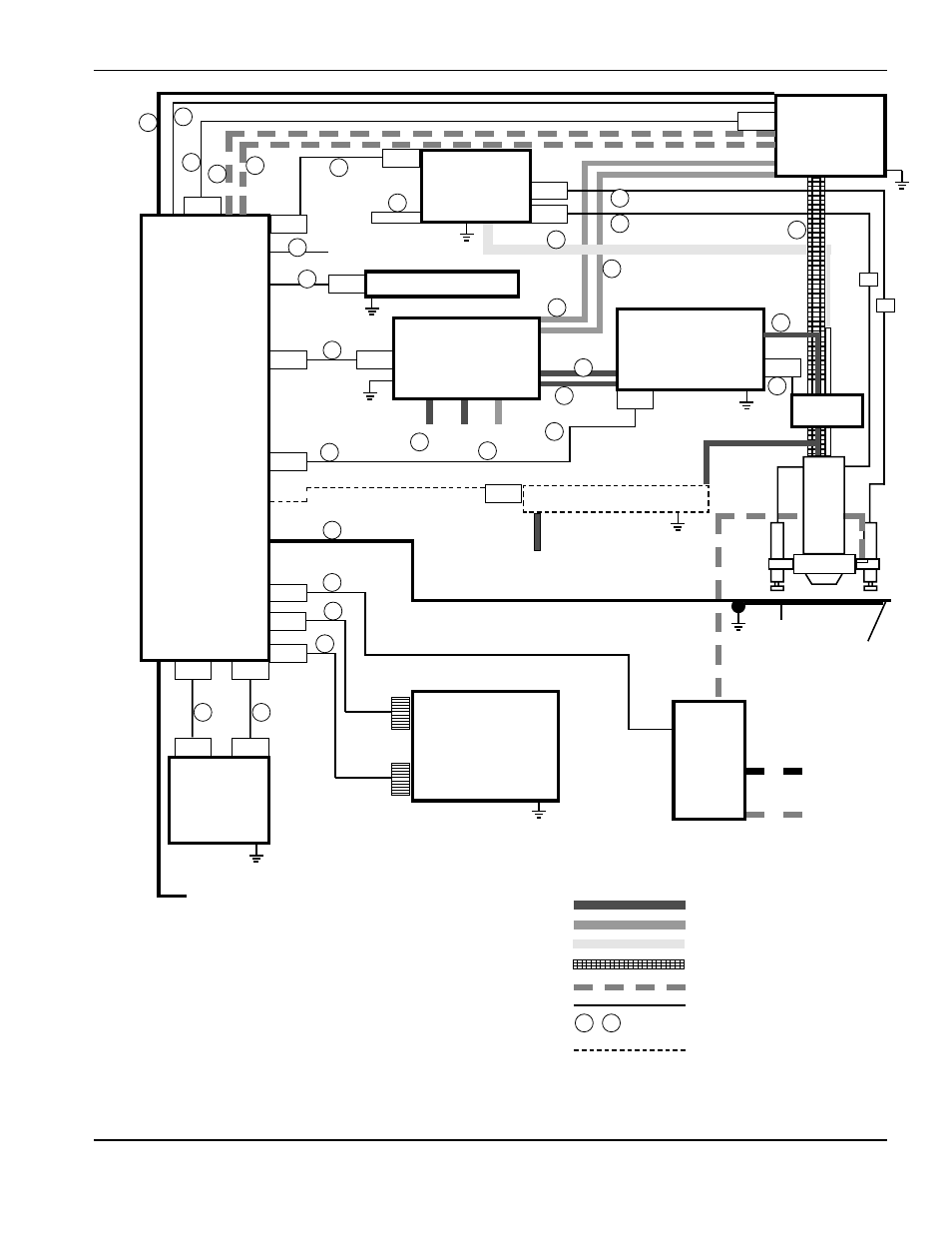
Figure 4-3
HT2000 Interconnect System Diagram with IHS and Water Muffler
RHF
Console
IHS
Console
Timer/Cntr
Gas
Console
Ar-H
2
Manifold
Motor
Valve
Console
Water
Muffler
Pump
Power
Supply
Remote
V/C
Machine
Computer
Interface
2X1
1X1
1X9
3X1
1X2
1X3
14X1
4X1
1X7
1X4
1X5
5X1
5X2
1X6
1X10
11X1
8X1
8X3
4X2
8X2
Work table
Workpiece
25
25
24
21
20
22
23
19
18
Off Valve
8X5
8X4
3-Phase
Power
3-Phase
Power
H
2
O
in
1
3
13
15
14
14
16
27
26
6
7
2
8
9
10
11
12
4
5a
5b
Air in
To Second
Power Supply
17
Key
Plasma gas hosing
Shield gas hosing
Air hosing
Shielded torch leads
Water cooling hosing
Cables
Reference to installation steps
See Section 7
, etc.
19
5
Advertising
This manual is related to the following products: