4 connectors, Serial port 1, Connecting a programming device – Yaskawa MP940 User Manual
Page 101: Connector pin arrangement and signal names
MP940 Functions
4.2.4 Connectors
4-8
4.2.4 Connectors
Serial Port 1
The MP940 can communicate with communications devices on the MEMOBUS Network
by means of RS-232C via serial port 1.
Connect a Programming Device (a personal computer with an RS-232C interface) to serial
port 1.
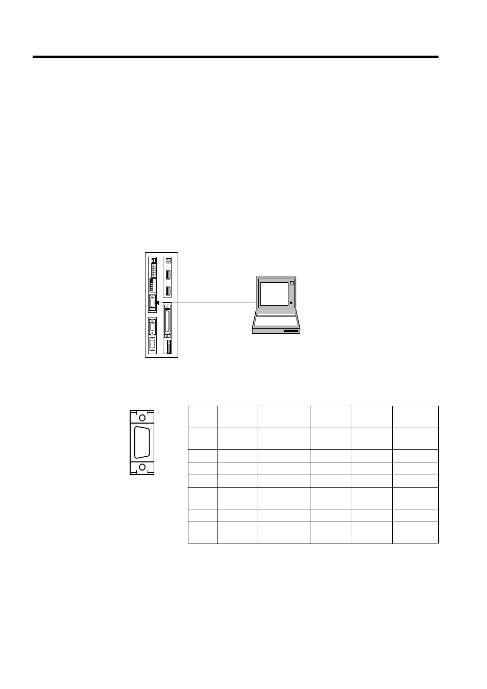
Connecting a Programming Device
The following diagram shows an example of a Programming Device connected to serial port
1.
Connector Pin Arrangement and Signal Names
The following table shows the connector pin arrangement and signal names for serial port 1.
• Connector at Module: 10214-52A2JL (3M)
• Connector at Cable: 10114-3000VE (3M)
• Shell: 10314-52A0-008 (3M)
CP-717
BAT
RDY
RUN
ALM
BAT
PRT1
6
5
4
3
2
1
NO
→
PRT2
RUN
INIT
TEST
FLASH
PP
COPY
PORT1
PORT2
POWER
+24V
GND
FG
LED
I/O
TX
R
X
1
2
M
E
C
H
A
T
R
O
L
I
N
K
MP940
RS-232C
No.
Signal
Name
Remarks
No.
Signal
Name
Remarks
1
TXD
Transmission
data
8
2
9
3
RXD
Receiving data
10
4
11
5
12
RTS
Request to
send
6
CTS
Clear to send
13
-
7
14
GND
Signal
ground
PORT1