3 counter function configuration – Yaskawa MP940 User Manual
Page 124
4.4 CNTR Function
4-31
4
4.4.3 Counter Function Configuration
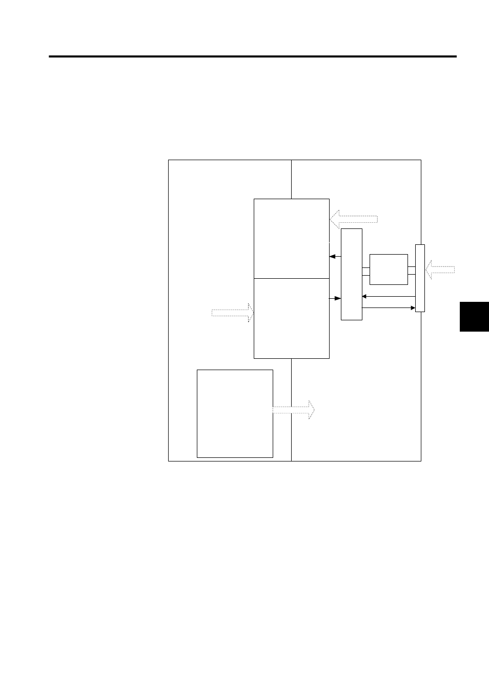
With the counter, functions selected by fixed parameters and output registers are executed
and status and counter values are stored in input registers.
The following diagram shows the data flow for the counter.
CPU
I/O
CNTR function
Virtual shared memory
Input registers
(16 words)
Operating status
Incremental pulses
Hardware counter
Other than latch data
Data from counter to CPU
Pulse inp
ut processor
5-V differ-
ential inter-
face
Latch input
Coincidence detec-
tion output
Pulse input
Commands from
CPU to counter
Output registers
(16 words)
Operating mode
Count preset data
Coincidence detec-
tion set value
Fixed parameters
Operation condition
setting for counter
function
Leading register number
A/B pulse signal form
selection
A/B pulse signal polarity
selection
Pulse count method
Counter mode
Other function selections