Yaskawa MP940 User Manual
Page 292
Parameters
6.4.2 Function Selection Constants
6-52
Pn003
Function
Selection
Application
Switches 3
0
Analog moni-
tor 1:
Torque refer-
ence monitor
(0 to 7)
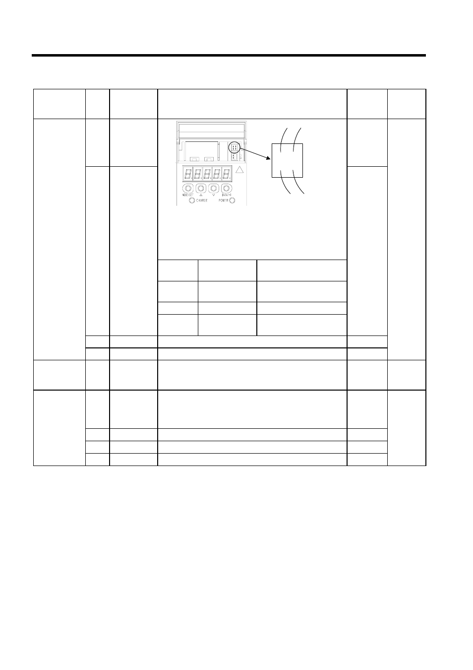
You can change the analog monitor signal by setting parameters
Pn003.0 and Pn003.1. If an MP940 is connected, be sure to make
the following settings.
• Pn003.0: 2 Torque reference monitor
• Pn003.1: 0 Motor rotation speed monitor
2
Speed
Torque
Control
1
Analog moni-
tor 2:
Speed refer-
ence monitor
(0 to 7)
0
Cable
Color
Signal Name
Description
White
Analog monitor 1 Torque reference: 1 V/100%
rated torque
Red
Analog monitor 2 Motor r/min: 1 V/1000 r/min
Black (two
wires)
GND (0V)
-
2
Reserved
0
3
Reserved
0
Pn004
Reserved
Parameters
0 to 3 513 to 32768
Do not set.
0
Speed
Torque
Position
Pn005
Function
Selection
Application
Switches 5
0
Brake Con-
trol Function
Selection
(0, 1)
If connecting an MP940, be sure to set to 0.
0: Use SERVOPACK brake sequence.
1: Use host controller brake sequence.
0
Speed
Torque
Position
1
Reserved
0
2
Reserved
0
3
Reserved
0
Parameter No. Digit
Name
(Setting
Range)
Details
Default
Control
Modes
CN5
White Red
Black Black