6 servopack i/o signals, 1 examples of i/o signal connections, Use ext3 as the latch input signal – Yaskawa MP940 User Manual
Page 209
Advertising
5.6 SERVOPACK I/O Signals
5-37
5
5.6 SERVOPACK I/O Signals
This section describes I/O signals for the SGDH SERVOPACK.
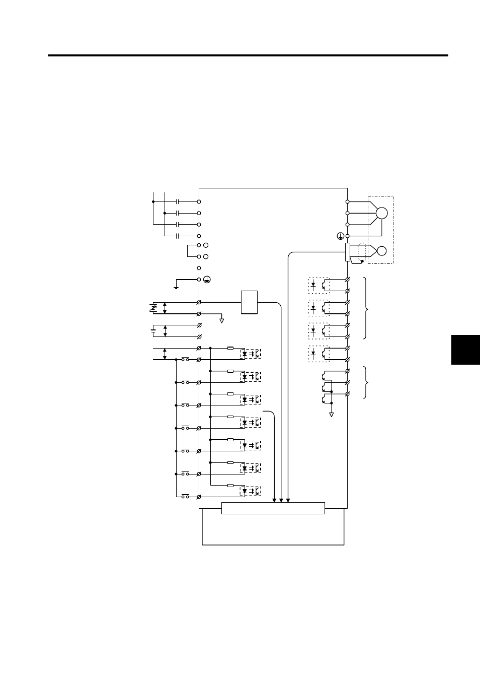
5.6.1 Examples of I/O Signal Connections
The following diagram shows a typical example of I/O signal connections.
∗ 1.
If using the ZERO signal for zero point return, connect the ZERO sig-
nal to EXT2.
∗ 2.
Use EXT3 as the latch input signal.
L1
L2
LC1
LC2
+
+
1
2
P
5
6
V-REF
SG
P
21
22
BAT(+)
BAT(-)
SGDH
+24V
DEC
P-OT
N-OT
EXT1
EXT3
∗2.
47
40
41
42
43
44
45
46
33kΩ
W
V
U
M
PG
CN2
~
25
26
~
27
28
~
29
30
~
31
32
37
38
39
共有メモリ
A/D
SO1
SO2
SO3
ALM+
ALM-
ALO1
ALO2
ALO3
MP940
Motor
Output signals
can be mapped
using settings
Pn50E to Pn510.
Servo alarm output
Alarm code output
Maximum operating volt-
age: 30 VDC
Maximum operating cur-
rent: 20 mA DC
General use
Shared memory
EXT2*
1
Advertising