Serial port 1 (rs-232c) connection – Yaskawa MP940 User Manual
Page 191
5.3 Connection Methods
5-19
5
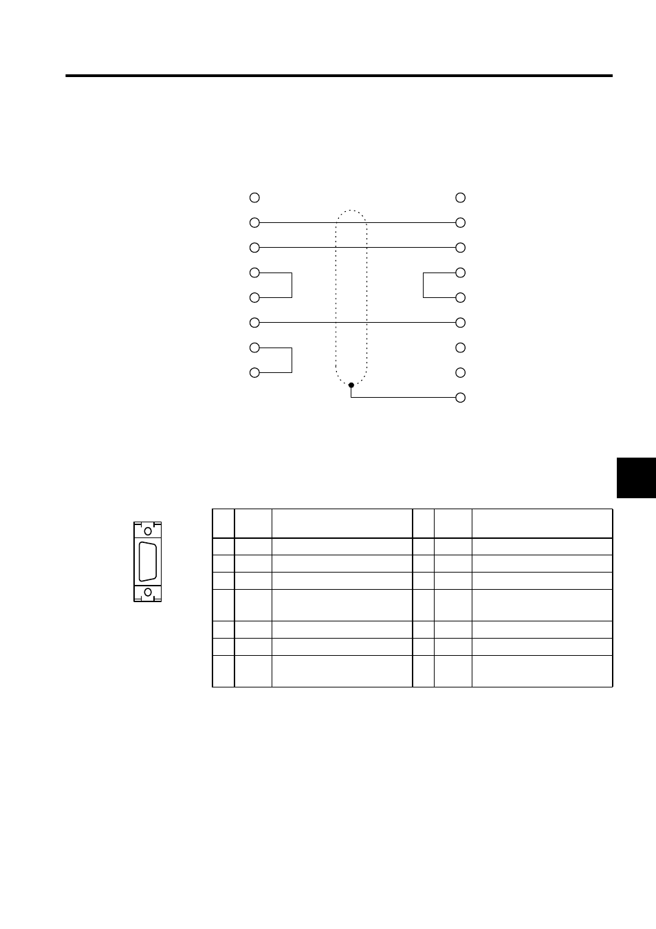
Serial Port 1 (RS-232C) Connection
The serial port 1 (RS-232C) connection is shown below.
Serial Port 2
Connector Pin Arrangement and Signal Names
The following table describes the serial port 2 connector pin arrangement and signal names.
∗ 1.
The terminating resistance (100 ) is connected by connecting to
RX( ).
∗ 2.
The terminating resistance (100 ) is connected by connecting to
TX( ).
NC
RXD
TXD
RTS
CTS
GND
DTR
DSR
1
2
3
7
8
5
4
6
1
3
12
6
14
TXD
RXD
RTS
CTS
GND
MS/DOS computer
MP940
Clamp on hood
No
.
Signal
Name
Remarks
No
.
Signal
Name
Remarks
1
TX +
Transmit data positive side
8
TX +
Transmit data positive side
2
TX -
Transmit data negative side
9
TX -
Transmit data negative side
3
RX +
Receive data positive side
10 RX +
Receive data positive side
4
RX -
Receive data negative side
11
TXR
Transmit data terminating ressis-
tance
*2
5
12
6
RX -
Receive data negative side
13 VCC
Power supply (+5 V)
7
RXR
Receive data terminating resis-
tance
*1
14 GND
Signal ground
PORT2
Ω
–
Ω
–