Serial port 1, Connecting a programming device, Connector pin arrangement and signal names – Yaskawa MP940 User Manual
Page 178
System Startup
5.2.1 MP940 Module
5-6
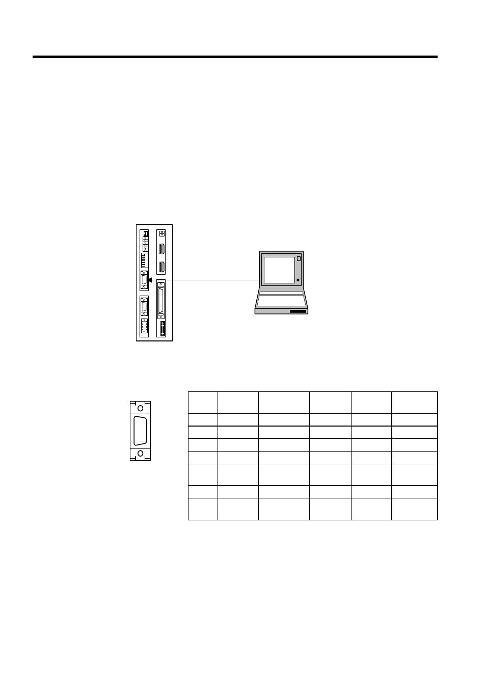
Serial Port 1
The MP940 Module can perform communications using RS-232C with communications
devices on a MEMOBUS network via serial port 1.
Connect a Programming Device (a personal computer equipped with a RS-232C interface)
to serial port 1.
Connecting a Programming Device
The following diagram shows an example of a Programming Device connected to serial port
1.
Connector Pin Arrangement and Signal Names
The following table lists the serial port 1 connector pin arrangement and signal names.
No.
Signal
Name
Remarks
No.
Signal
Name
Remarks
1
TXD
Transmit data
8
2
9
3
RXD
Receive data
10
4
11
5
12
RTS
Request to
send
6
CTS
Clear to send
13
-
7
14
GND
Signal
ground
CP-717
BAT
RDY
RUN
ALM
BAT
PRT1
6
5
4
3
2
1
NO
→
PRT2
RUN
INIT
TEST
FLASH
PP
COPY
PORT1
PORT2
POWER
+24V
GND
FG
LED
I/O
TX
R
X
1
2
M
E
C
H
A
T
R
O
L
I
N
K
MP940
RS-232C
PORT1