Ladder logic program example – Yaskawa MP940 User Manual
Page 420
Motion Control
11.2.4 Phase Control Mode
11-18
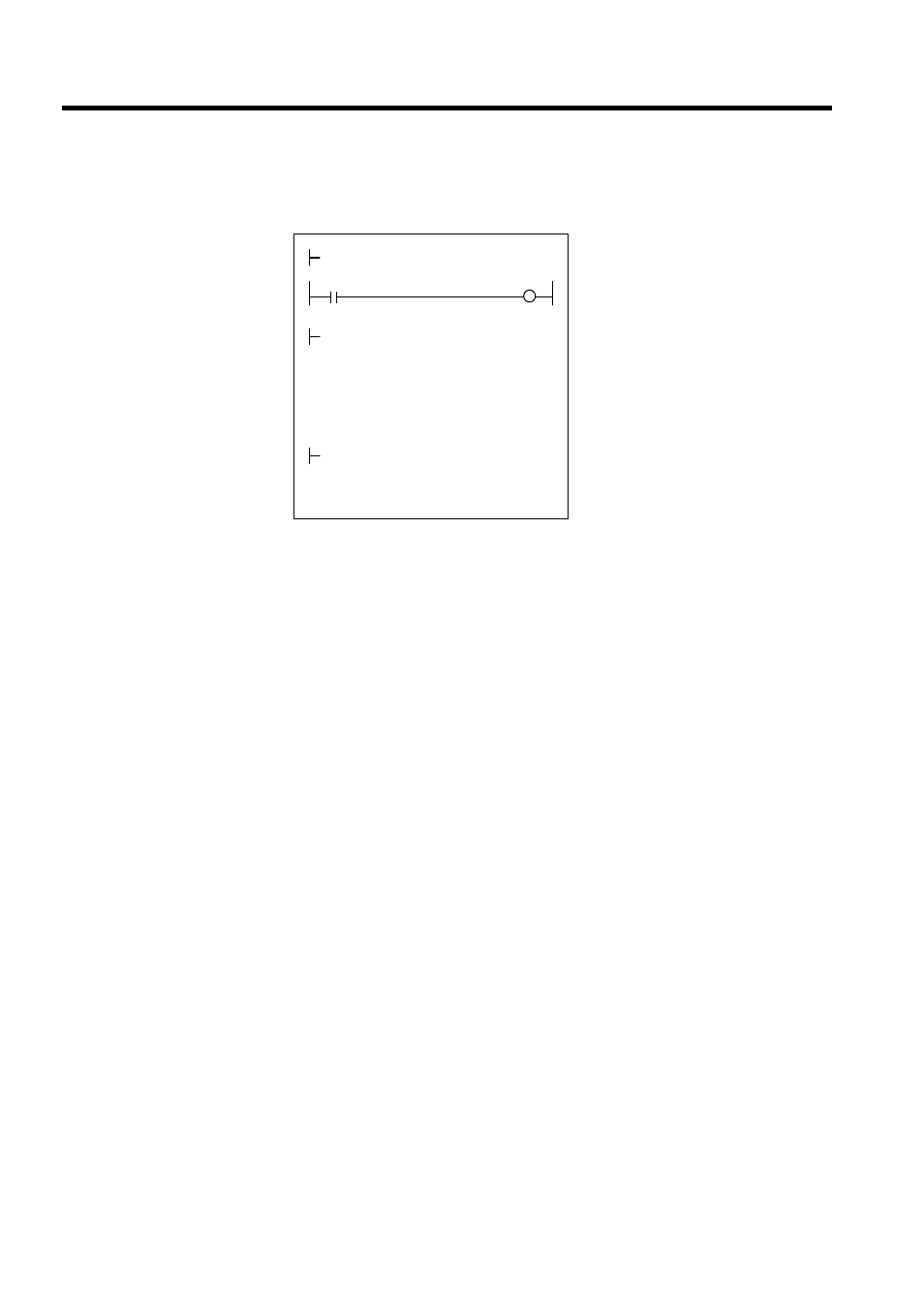
Ladder Logic Program Example
Fig 11.9 RUN Commands (DWG H04)
The example in the illustration on the previous page has been greatly simplified. In actual
operation, each register can be controlled from the user program.
RUN
OBC0010
PREPARE
MB010010
MW01010×MW01020+ML02012
VERF
GEAR1
AMARI
÷
MW01021
GEAR2
NREF
⇒
OWC015
MOD
×
00001
AMARI
⇒
ML02012
ML01012
PHBIAS
⇒
OLC016
ISO-HOSE
DEND
H0108
RUNMOD
⇒
OWC000
Set the phase control mode to ON.
Set Phase Reference Generation
Operation Disable to OFF.
Driver RUN command (RUN)
When MB01010 turns ON, phase con-
trol starts.
Set the reference speed reference
(NREF).
The speed reference is stored in
advance in MW01010. The gear ratios
are stored in advance in MW01020 and
MW01021. If gears are not required, “1”
is stored in advance.
To move the phase, set the phase com-
pensation (OLC016). The distance to be
moved (the angle of rotation of the
motor axis converted to the number of
pulses) is stored in advance in
ML01012.