Pn005.0: brake control – Yaskawa MP940 User Manual
Page 167
MP940 Functions
4.7.4 Setting Parameters of the SGDH SERVOPACK
4-74
Pn005.0: Brake Control
Parameter
Set Value
Details
Default
Setting
Pn005.0
0
Brake Control Function Selection
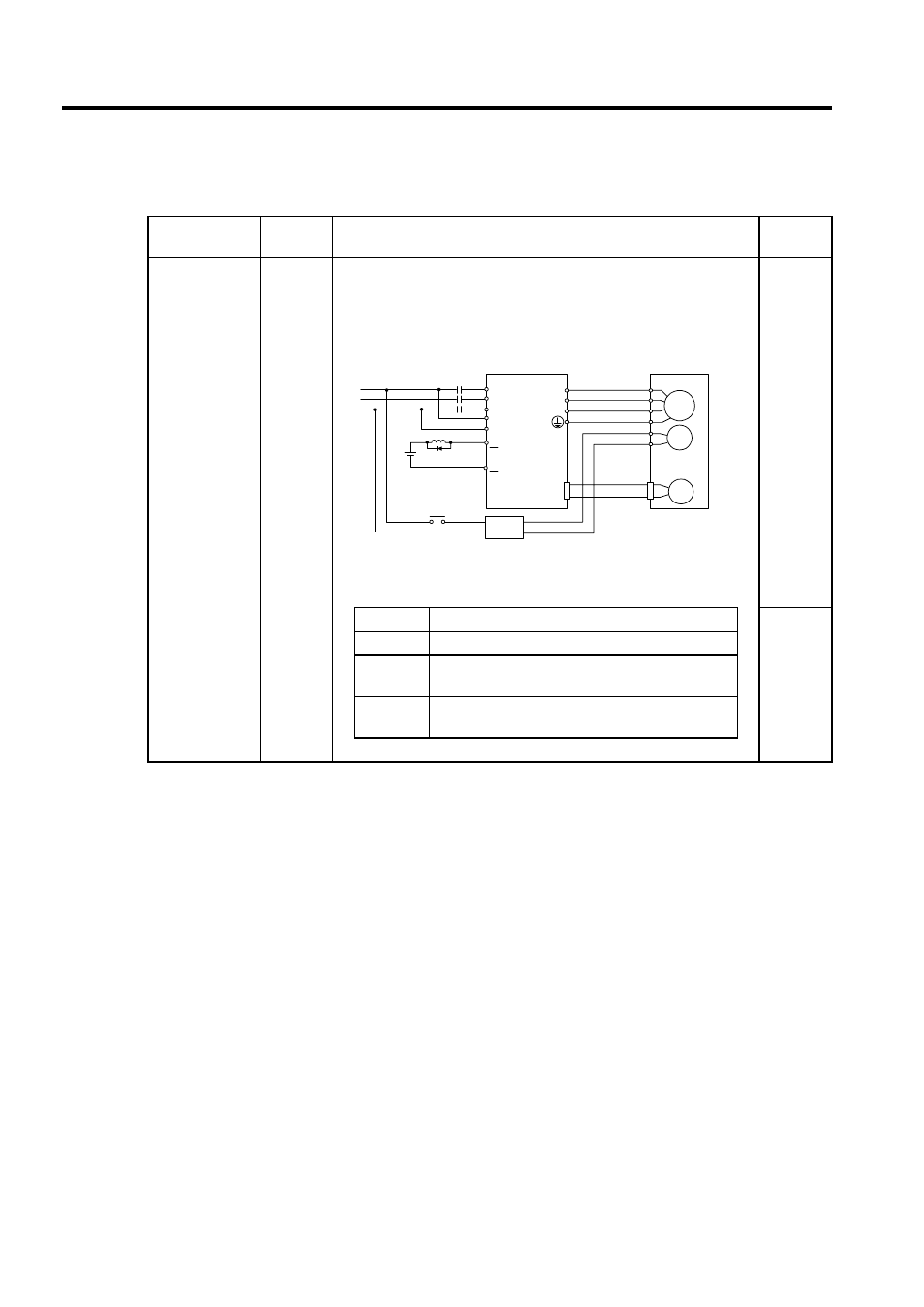
Use Pn005.0=0, SERVOPACK brake sequence.
Use the SERVOPACK contact output signal /BK and the brake power sup-
ply to form a brake ON/OFF circuit. The following diagram shows a stan-
dard wiring example.
Related Parameters
0
Pn50F2
Output Signal Selections 2
Pn506
Time Delay from Brake Reference until Servo OFF
Pn507
Speed Level for Brake Reference Output during
Motor Operation
Pn508
Timing for Brake Reference Output during Motor
Operation
Refer to Chapter 6 Parameters for details.
M
BK
PG
A(1)
B(2)
C(3)
D(4)
E(5)
F(6)
U
V
W
CN2
AC
DC
BK-RY
BK-RY
+24V
L1
L2
L3
L1C
L2C
CN1-*2
CN1-*1
/BK+
/BK-
Power supply
SERVO-
Blue or
yellow
White
Red
Black
Brake Power Supply
BK-RY: Brake control relay
*1 and *2 are the output terminals allocated with Pn50F.2.
Brake power supplies are available for either 200 V or 100 V.