2 part names, 1 mp940 module, Led 1 indicators – Yaskawa MP940 User Manual
Page 176: Led1 indicators show the module’s status
System Startup
5.2.1 MP940 Module
5-4
5.2 Part Names
This section provides the names of the parts of the MP920 and a general explanation of each
part.
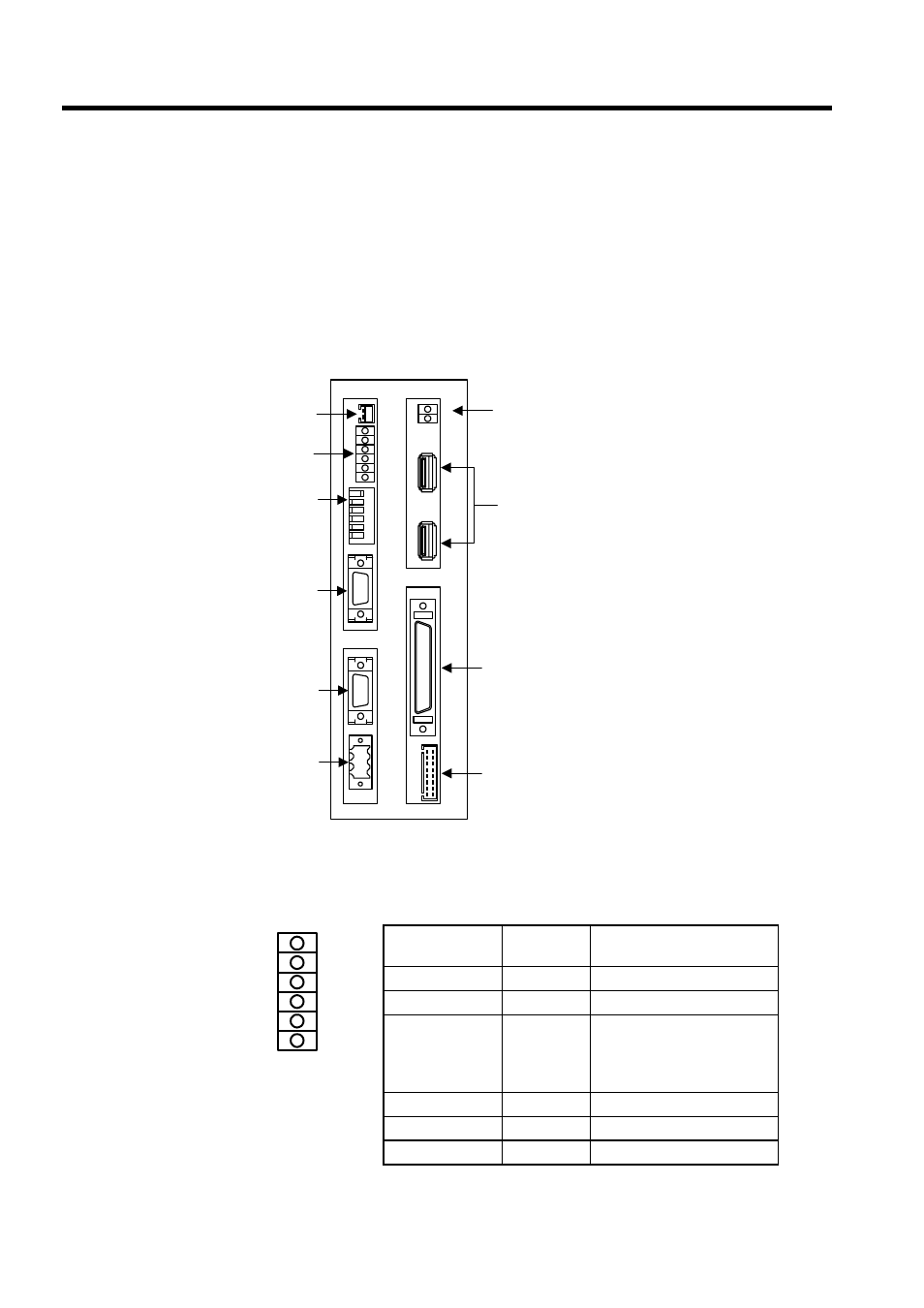
5.2.1 MP940 Module
The following illustration shows the appearance of the MC400 MP940 Module.
LED 1 Indicators
LED1 indicators show the Module’s status.
BAT
RDY
RUN
ALM
BAT
PRT1
6
5
4
3
2
1
NO
→
PRT2
RUN
INIT
TEST
FLASH
PP
COPY
PORT1
PORT2
POWER
+24V
GND
FG
LED
I/O
TX
RX
1
2
M
E
C
H
A
T
R
O
L
I
N
K
MP940
LED1
LED2
Battery
connector
DIP
switch
Serial
port 1
Serial
port 2
Power
supply
connector
MECHATROLINK
connectors
I/O connector
LED indicator
connector
LED2 indicators
LED1
indicators
Name
Indicator
Color
Meaning when Lit or
Flashing
RDY
Green
System operating normally.
RUN
Green
Program running.
ALM
Red
Lit: Minor system failure
occurred.
Flashing: System fault or fail-
ure occurred.
BAT
Red
Battery needs replacing.
PRT1
Green
Serial port 1 sending data.
PRT2
Green
Serial port 2 sending data.
RDY
RUN
ALM
BAT
PRT1
PRT2