Yaskawa MP940 User Manual
Page 190
System Startup
5.3.3 Serial Port Connector Pin Arrangements and I/O Circuits
5-18
5.3.3 Serial Port Connector Pin Arrangements and I/O Circuits
Serial Port 1
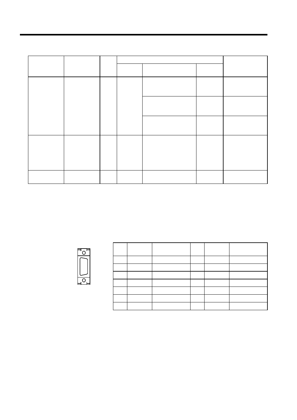
Connector Pin Arrangement and Signal Names
The following table describes the serial port 1 connector pin arrangement and signal names.
• Module connector: 10214-52A2JL (3M)
• Cable connector: 10114-3000VE (3M)
• Shell: 10314-52A0-008 (3M)
MECHATRO-
LINK connector
MECHATRO-
LINK
4
DUSB-
ARA41-
T11
• Connector
DUSB-APA41-B1-C50
• USB to USB type
DDK
JEPMC-W6000-A3
• Connector
DUSB-APA41-B1-C50
• USB to loose wire type
DDK
JEPMC-W6010-01
JEPMC-W6010-03
JEPMC-W6010-05
• Connector
DUSB-APA41-B1-C50
• USB terminator
DDK
JEPMC-W6020
I/O connector
I/O
50
10250-
52A2JL
• Connector
10150-3000VE
• Shell
10350-52A0-008
3M
JZMSZ-
120W0402-01
JZMSZ-
120W0402-03
JZMSZ-
120W0402-05
LED indicator
connector
LED
16
IMSA-
9220B-16A
−
−
−
Name
Connector
Name
Number
of Pins
Connector
Cable
On Module
On Cable
Manufac-
turer
No.
Signal
Name
Remarks
No.
Signal
Name
Remarks
1
TXD
Transmit data
8
2
9
3
RXD
Receive data
10
4
11
5
12
RTS
Request to send
6
CTS
Clear to send
13
-
7
14
GND
Signal ground
PORT1