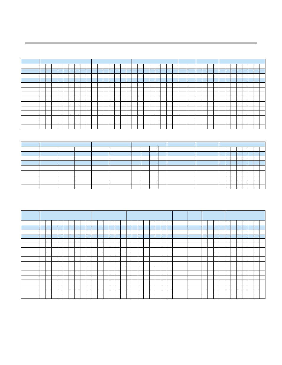
Appendix 6. spares, A6-1 – Yaskawa GPD503 Drive User Manual
Page 148

Appendix 6. SPARES
A6-1
6
6
1
1
DS305
DS302
DS306
DS307
DS308
DS309
DS310
DS311
DS322
DS323
Part No.
502078__
501848__
501739__
Model No.
DC Bus Fuse
1
1
DS313
DS304
DS314
DS315
DS316
DS317
DS318
DS326
DS325
DS330
DS340
DS350
DS360
2
2
2
2
2
2
2
2
2
2
2
2
2
1
Transistor Module
Diode Module
Diode Module
Control
PCB
Fan
DC Bus Fuse
02 03
05 06 07 08 09 10 20 21 22 23 24
16
34 35 36 37
46
56
57
47
02
28 29 30 31
36
1
1
3
04
3
1
1
1
1
1
1
1
1
1
1
1
1
1
1
1
1
1
1
1
1
1
1
1
1
1
1
1
1
1
1
1
1
1
1
1
1
1
1
1
1
1
1
1
1
GPD 503 - 230 VAC Rating - 1HP CT (1HP VT) thru 30HP CT (40HP VT)
62
Base Drive PCB
Base Drive PCB
30 31 32 33
01
32 59
49
1
1
1
1
1
1
1
1
1
1
1
1
3
3
3
1
1
3
36
63
62
35
52
51
50
48
01
46
Fan
57
53
43 44
42
Control
PCB
60 61 62
59
18
17
28
27
26
25
18
17
15 16
14
13
11 12
Transistor Module
1
1
1
1
1
1
1
1
1
1
1
1
1
1
1
1
1
1
1
1
1
1
1
1
1
1
1
1
1
1
1
1
1
1
1
1
1
1
1
1
1
1
1
1
1
1
1
1
1
1
1
1
1
1
1
1
3
3
3
3
1
1
1
1
1
1
1
6
6
19
6
3
3
3
3
3
3
3
1
1
1
45
1
GPD 503 - 460 VAC Rating - 1HP CT (1HP VT) thru 60HP CT (75HP VT)
02
Part No.
502078__
501848__
501739__
Model No.
Chopper
PCB
3
IMPORTANT
Numbers represent total quantity used in the Drive. To determine Spares List, factory
suggests using listed value for quantities 2 and below. If listed value is greater than 2,
factory suggests 1/3 of total.
DS2040
DS2050
DS2060
DS2075
DS2100
Transistor Module
Diode Module
Fan
DC Bus Fuse
05
06
12
36
58
19
20 21
60
6
12
12
6
12
2
2
2
2
2
1
1
1
1
1
1
1
1
1
GPD 503 - 230 VAC Rating - 40HP CT (50HP VT) thru 100HP CT (125HP VT)
Gate Driver PCB
Control PCB
35
90
1
1
49
1
50
1
1
1
3
6
6
6
9
Part No.
502079__
501848__
502078__
Model No.