36 carrier frequency – Yaskawa GPD503 Drive User Manual
Page 91
2.36 CARRIER FREQUENCY
Cn-23: Carrier Frequency Upper Limit
Factory Setting: See Table 2-5
Cn-24: Carrier Frequency Lower Limit
Range (Each): 0.4 to 15.0 kHz
Cn-25: Frequency Proportion Gain
Factory setting: See Table 2-5
Range: 0 to 99
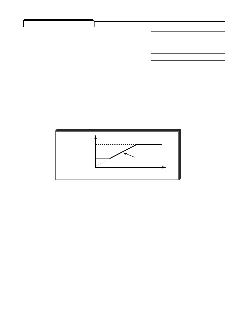
The relationship between output frequency and carrier frequency is determined from the
set values of Cn-23 to Cn-25.
(a)
For constant carrier frequency (set value of Cn-23):
Set Cn-25 to 0, and set the same value in both Cn-23 and Cn-24.
(b)
For synchronous mode (only with proportional section):
Set Cn-25 to 12, 24, 36 or 48. These setting values establish carrier frequencies of
12f, 24f, 36f, or 48f, respectively.
NOTE: Fault code
oPE I I
is displayed if either of the following conditions is
detected:
1.
Cn-25 > 6 kHz, and Cn-24 > Cn-23
2.
Cn-23 > 5 kHz, and Cn-24
) 5 kHz.
2-52
Changed
Cn-23
CARRIER
FREQUENCY
PROPORTIONAL
Cn-24
SECTION
0
OUTPUT FREQUENCY